|
NOTES AND
EXTRACTS
ON THE HISTORY OF THE
LONDON & BIRMINGHAM RAILWAY
CHAPTER 8
CONSTRUCTION
―
CHEDDINGTON TO BIRMINGHAM
PITSTONE AND CHEDDINGTON

Cheddington
station, looking north - the long embankment.
|
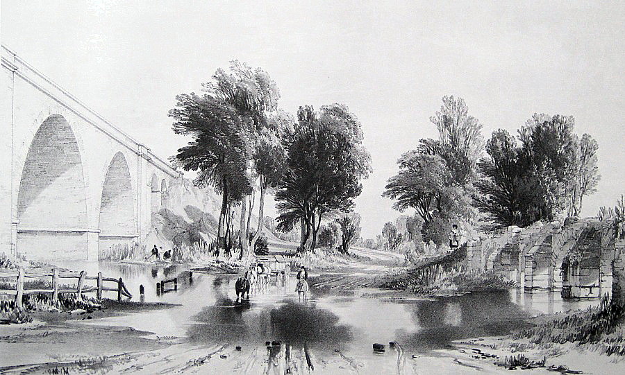
The embankment to the north of the Tring Cutting is, with the
inclusion of short cuttings, some six miles long and 30 feet high in
places, much of the 1.4 million cubic yards of chalk used to form it
having being excavated from Tring Cutting. At Pitstone (Cook’s
Wharf), the Grand Junction Canal is bridged by one of the line’s
formerly
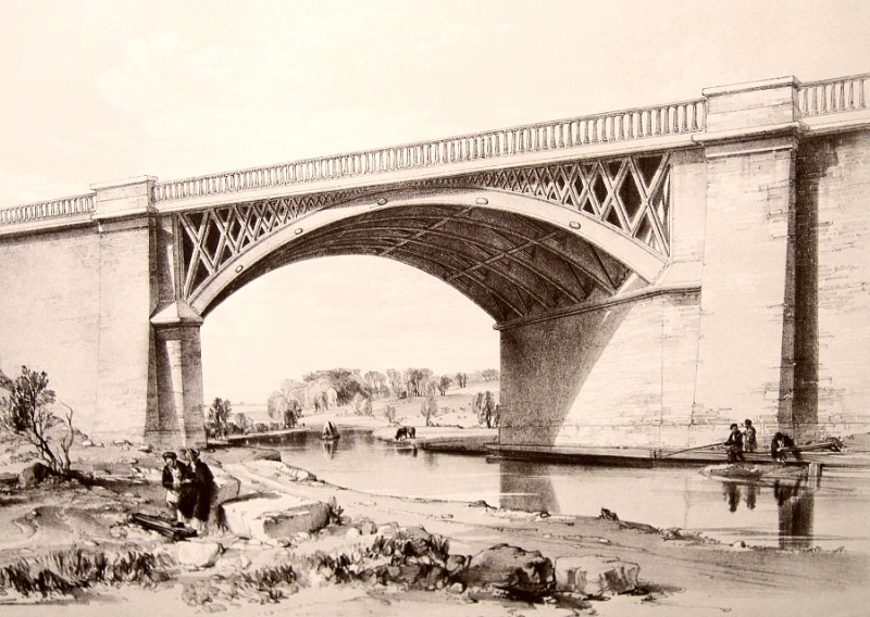
attractive iron segmental arch skew bridges, depicted below by
Bourne in its original condition. |
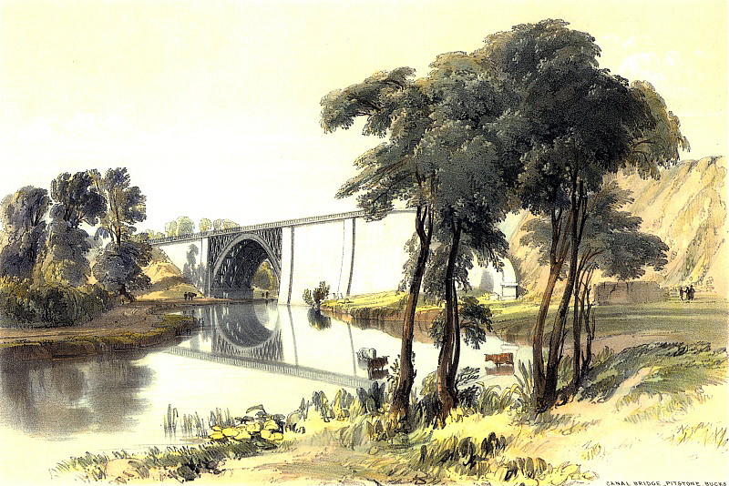
West side of an iron bridge over the
Grand Junction Canal near Pitstone, with lofty embankment.
John Cooke Bourne, 1837.
Below, the unappealing view today.

|
Built to carry two tracks, the original bridge was widened on its
eastern side, first (ca. 1859) by the addition of a third track and
again (ca. 1876) with a fourth. During this widening, the
bridge’s brick abutments were rebuilt and then, in the British Rail
modernisation era, its cast iron arches were replaced with
reinforced concrete ― the outcome, shown above, is, as one might
expect, unappealing. The land on the right of Cooke Bourne’s
illustration now houses Cook’s Wharf Marina. |
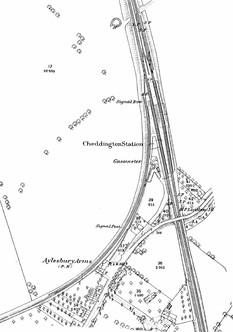
Cheddington
Station and the junction with the Aylesbury Railway.
|
“. . . . the Aylesbury railway is on the
left; it is seven miles in length; has only one line of rails; is
nearly level from end to end; and has no curve, except at its
junction with the main line. An Act was passed in 1836 to
incorporate the Company, and to make this branch line; which was
planned and directed by Robert Stephenson, Esq.; and was opened on
the 10th June, 1839. It is rented by the London and Birmingham
Railway Company, for five years, at £2,500 per annum. The Vale
of Aylesbury, which surrounds the town, has long been noted for its
extensive and fertile grazing farms, its prolific arable fields, and
for other agricultural distinctions.”
Historical and Descriptive Accounts of the the London and Birmingham
Railway, John Britton (1839).
Some 2-miles north of the Cook’s Wharf canal bridge is the site of
the former junction with the Aylesbury Railway. This branch
line, the U.K.’s first, left the main line in a southerly direction
before veering to the south-west to follow a straight course across
the Vale to Aylesbury. Construction began in May 1838 and the
line opened in June of the following year. It had one
intermediate station at Marston Gate (one mile north of Long Marston
and 2½-miles from Cheddington). [1] Its
proprietors’ ambition was to extend the line to Oxford, and with
that in mind they bought sufficient land to accommodate double
tracks, but nothing came of their plan and the line remained single.
|

Cheddington
station in the 1950s looking north. The Aylesbury branch is on
the left of the picture.
|
The Aylesbury Railway closed to passengers in 1953 and to freight in
1964. Oddly, its erstwhile competitor, the Aylesbury Canal ―
whose trade was much damaged by the railway ― somehow managed to
struggle on into the canal preservation era. Its basin now
forms the hub of a major property development just off Aylesbury
town centre and a marina has opened nearby.
A short distance to the north of Cheddington, another of the line’s
bridges, No. 127 near Ledburn (a.k.a. as Bridego Railway Bridge),
gained notoriety when, in 1963, it became the scene of the robbery
of a Glasgow to London mail train, which was brought to a halt
through the robbers tampering with the line’s colour light signals.
The bulk of the £2.6 million stolen in what became known as the
‘Great Train Robbery’ was never recovered ― neither did Jack Mills,
the train’s driver, ever recover from the head injuries he sustained
during the holdup.
――――♦――――
LINSLADE
The long embankment continues to Linslade where, just north of
Leighton Buzzard station (actually within Linslade), the line enters
a cutting and the short Linslade Tunnel. Greensand Ridge,
under which the tunnel passes, is part of a range that extends
across Bedfordshire by the Brickhills, to Woburn, &c. It
consists of a deep stratum of indurated red sand, with bands of iron
stone and occasional beds of fuller’s earth:
“Immediately after leaving the Leighton
Station the train enters the Linslade Tunnel, which is cut through
the blue clay and iron sand: it is 284 yards in length, and curves
rather to the left, and is ventilated by one shaft: at the end there
is a deep cutting through the iron sand rock, which stands in steep
yellow walls, forty feet high at each side of the line. Just
afterwards a bridge crosses the line, over which is the road from
Leighton to Stoke Hammond; and then we may obtain, on the right a
momentary glimpse of a scene the most striking of any on the line;
it consists of a valley bordered by hills and cliffs of the yellow
sand rock, round the side of which winds the canal; at the bottom is
a streamlet bordered by willows; the whole well wooded, and the
distant hill tops crowned by a dark heath. The bright
appearance of the sand rock has a peculiar effect, and gives the
whole scene a panoramic appearance that cannot but attract
attention.”
Osborne’s
London & Birmingham Railway Guide, E.C. and W. Osborne (1840).
None of the colours described in Osborne are evident today. |

Blasting the
rocks to form an excavated passage, at Linslade.
John Cooke Bourne, October 1837.

Linslade Tunnel
before two further bores were opened to accommodate four tracks.
|
The Grade II listing describes the northern entrance to Linslade
Tunnel thus:
“Red
brick castellated retaining wall with 3 horseshoe arches in moulded
surrounds, central arch taller, 3 semi-octagonal embattled turrets.
An interesting example of early railway architecture.”
English Heritage
(list entry number: 1114529). |

Northern entrance to Linslade Tunnel.
The central bore is Stephenson’s
original, the outer bores were added when the track was tripled in
1859 and quadrupled in 1876.
|
The Tunnel’s southern entrance (also Grade II-listed) is a less
elaborate affair.
Linslade Tunnel,
southern portal of the original bore.
――――♦――――
THE WOLVERTON EMBANKMENT
From Linslade the Railway, the Grand Junction Canal and the River
Ouzel keep close company as they make their way northwards until, at
Bletchley, they diverge. The Railway then heads directly for
Wolverton while the canal and river follow the contour around the
eastern side of Milton Keynes until, at Newport Pagnell, the Ouzel
flows into the Great Ouse. The Canal then veers westwards
towards Wolverton where, just north of the station, it passes
underneath the Railway. At this point Barnes and Stephenson
were both faced with the challenge of taking their respective
highways across the valley of the Great Ouse. Barnes crossed
upstream of the Railway, near the village of Cosgrove, on a massive
earth embankment, the Canal being carried over the Great Ouse in
Benjamin Bevan’s iron trough aqueduct (1812). Stephenson also
employed a massive earth embankment ― much longer than its neighbour
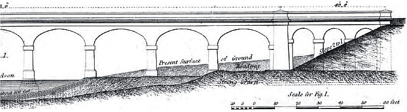
― crossing the Great Ouse on a substantial brick viaduct.
|

West side of the viaduct over
the River Ouse, near Wolverton.
By John Cooke Bourne, August 1837.
|
“At this Station [Wolverton]
the railway crosses the Grand Junction Canal, for the fourth time,
by an iron bridge with horizontal main ribs, and then enters the
great Wolverton Embankment, which extends across the valley of the
[Great] Ouse to an extent of one mile and a
half, being the longest on the line: it averages 48 feet in height,
and is composed chiefly of clay, gravel, sand and lias limestone.
In its course is a viaduct consisting of six principal arches, of an
elliptical form, having a span of 60 feet each, and rising 46 feet
from the ground to the crown. In the abutment of each of the
viaduct, are two bold pilasters, and four subordinate arches: a
stone cornice runs through the whole, which is 660 feet in length,
and 57 feet high on top of the parapet. Beneath one of the
main arches is an artificial channel, formed by the Company, for the
united waters of the River Ouse and a smaller stream called the Tow,
which formerly flowed separately through the valley.”
Historical and Descriptive Accounts of the the London and Birmingham
Railway, John Britton (1839).
Whereas the Primrose Hill Tunnel was the first of Stephenson’s major
civil engineering headaches, the Wolverton Embankment became the
second:
“The Wolverton embankment, another of the
contracts which came back to the Company for completion, gave the
engineer much anxiety. In an embankment a mile and a half
long, exclusive of the Wolverton viaduct, some difficulty was
anticipated; but human foresight could not have provided for all the
disasters attending its construction. The embankment on the
north side of the viaduct gave comparatively little trouble.
Composed of blue clay, lias, limestone, gravel, and sand, it stood
well, except at one place where it slipped, not from its own
weakness, but because the ground gave way beneath its enormous
weight. On the south side of the viaduct, however, a grievous
mishap occurred, in the form of ‘a slip’ that was not overcome for
months.”
The Life
of Robert Stephenson, F.R.S., John Cordy
Jeaffreson (1866).
Initially, stable material not dissimilar to that used for the
northern section of the embankment was brought up from a cutting
being formed at Denbigh Hall, some three miles to the south.
It stood well, but as work on the cutting progressed, Oxford clay
was encountered. When this was added to the embankment, it was
found that it would not support the load and, as tipping progressed,
the embankment began to spread. To compensate, more material
was added, but the spreading continued:
“The length of the embankment being one
mile and twenty-eight chains, (deducting the viaduct) [80
chains in a mile] and the height of a great
part of it forty-eight feet, some accidents were to be expected,
especially in bad weather; but no one could have imagined what would
take place on the south side of the viaduct.
Here the material, at the commencement . . . . stood very well; but
when we got deeper into the [Denbigh Hall]
cutting, we worked out some black, soapy clay, very wet; this was
tipped onto a turf bottom, and the weather also being very
unfavourable, although every care was taken to mix dry stuff with
the wet material, yet there occurred one of the worst, if not the
worst slip along the whole line. Earth was tipped in for days
and days, and not the slightest progress was made; as fast, in fact,
as it was tipped in at the top it kept bulging out at the bottom,
till it had run out from 160 to 170 feet from the top of the
embankment . . . . ”
The History of
the Railway Connecting London and Birmingham, Lieut. Peter
Lecount R.N. (1839). |

View of the embankment near Wolverton, during its
progress:
shewing the manner of forming embankments,
and an accidental slip of earth.
John Cooke Bourne, June 1837.
|
At this point Lecount describes a temporary bridge being built to
enable tipping to continue on the far side of the slip, which is the
state of play depicted by Cooke Bourne above. A five feet deep
trench was then dug across the width of the embankment and mounds of
earth formed on each side to prevent the new formation from
slipping. However, the slip continued to give trouble:
“In fine summer weather the bridge was
removed, and that part of the embankment, where the slip had been,
was filled up; but away it went again, just as it did before, and
the yawning gulf appeared to be insatiable. It was months
before it was conquered, and this was done at last by barrowing as
much earth to the outer part of the slip, as would balance the
weight on top.”
The History of
the Railway Connecting London and Birmingham, Lieut. Peter
Lecount R.N. (1839).
Slippage was not the only problem encountered at the Wolverton
Embankment; spontaneous combustion was another, the outcome being
the unusual sight of a railway embankment on fire, the railway
sleepers adding to the blaze:
“No sooner was the way seen how to fill up
the slip, than Robert Stephenson was informed that the troublesome
embankment had caught fire. In its composition was a portion
of alum shale, containing sulphuret of iron [iron
sulphate]. This material decomposing
afforded a striking instance of spontaneous combustion. Great
was the consternation of the peasants at beholding a railway on
fire. Roguery was, they were convinced, at the bottom of the
catastrophe.”
The Life
of Robert Stephenson, F.R.S., John Cordy
Jeaffreson (1866).
Work at Wolverton was finally completed in April, 1838.
――――♦――――
THE BLISWORTH CUTTING
About 10-miles to the north of Wolverton, the Railway passes
through the Blisworth Cutting: [2]
“Immediately after entering
Northamptonshire the line of the Railway is obstructed by the
Blisworth ridge, which forms the division between the valley through
which we have come, and the valley of the Nene, a stream which rises
in the high lands near Daventry and runs east to Northampton.
The Grand Junction Canal is carried through a tunnel at Blisworth
3,080 yards in length. The Railroad avoids a tunnel but is
carried through an open cutting of limestone resting on a stratum of
rock. The rock has been ‘blasted’ with great labour and
expense.”
The Penny
Magazine (1838).
Approximately 1½ miles long and averaging 50 feet in depth, the
excavation was first estimated to contain some 800,000 cubic yards,
but subsequent widening increased this to over one million.
The contract for this section was let to William Hughes, an
experienced contractor whose curriculum vitae included work
on the Caledonian and Gotha (Sweden) canals. Hughes was faced
with a formidable task. At 1,400,000 cubic yards, the Tring
Cutting was the largest on the line and although flooding proved to
be a problem, the strata in the Chilterns is solid chalk. At
Blisworth, the excavation cut through three distinct strata; a mixed
layer of clays over 20 feet deep on average, overlying limestone,
under which lay yet more clay and waterlogged shale, although this
mix varied along the length of the cutting.
Work commenced in
March 1835, but progress was soon hampered by flooding.
According to Samuel Smiles, “for a year and a half the contractor
went on fruitlessly contending with these difficulties and at length
he was compelled to abandon the adventure”; Lecount is much less
sympathetic, “During the first year and a half the progress was
extremely slow, owing to the want of proper energy on the part of
the contractor, combined with general bad management.”
Whatever the reason, Hughes suffered a stroke and died, and by
December 1836 the work was back in the Company’s hands.
The
contract was then taken over by one of Stephenson’s assistants,
(later Sir)
Robert Rawlinson, George Phipps
being the Company’s resident engineer. Rawlinson attacked the
task with vigour, working his force of 700 to 800 men and boys
around the clock in an effort to bring the work back on schedule.
Steam pumps were erected to deal with the influx of water, gunpowder
was employed to shatter the limestone ― Lecount records that 25,
100lb barrels of gunpowder, were used each week ― and
locomotives were used at both ends of the cutting to remove the
excavated material to be used in the nearby Ashton and Blisworth
embankments.
“. . . . blasts of the rock continually
deafening the ear. In fact, the whole cutting seemed alive;
and the busy hum of labour, resounding from the one end to the
other, gave ample testimony to the zealous exertions of the engineer
. . . .
The mode of blasting made use of was by
drilling a hole in the stone, about one inch in diameter; the depth
was determined by the thickness of the bed. This is done by
means of a round iron bar shod with steel, which is lifted up, and
then struck down in the hole, water being used with it, causing the
stone to cut more readily, till the hole is drilled to the requisite
depth.
When the
hole is sufficiently deep, it is dried out; a piece of fuse, of the
requisite length, is then put in, and the gunpowder is poured all
round it, in the requisite quantity, and secured by a covering of
pounded brick and stone. Several charges being thus prepared,
the ends of the fuse are lighted, and the workmen retreat to a
sufficient distance for security. In a few minutes the whole
explode, tearing up large masses of the rock, and sending the
lighter pieces high into the air. The least noisy of these
explosions are generally the most effective, rending up the larger
masses of rock.”
The History of
the Railway Connecting London and Birmingham, Lieut. Peter
Lecount R.N. (1839).
In the southern and central sections of the cutting, the slopes were
at two gradients; 1:4 in the limestone (the lower shale in the
central section being contained by retaining walls) at the top of
which a 9 feet wide bench separated a shallower slope of 2:1 in the
upper levels of clay:
“The object of the benching was to catch
any loose portions of clay which might be detached from above; they
have also been found very useful as affording foundations for walls
of pebble-stone, which it has been found necessary to erect in many
places, to retain the numerous slips of clay above.”
The History of
the Railway Connecting London and Birmingham, Lieut. Peter
Lecount R.N. (1839).
Retaining wall to
be built in Blisworth Cutting.
An extract from the specification for the retaining walls in
Blisworth Cutting reads:
“. . . . The whole of the Walls and
Buttresses to be of masonry; the stones to be procured from the
excavations. The courses to run as thick as the material
obtained from the excavation will afford when properly quarried.
The facing stones to be at least 18 inches; the beds to be square
with the face of the buttress, or wall. The stones to be
hammer dressed, and brought to a rough bed, but perfectly true;
special care being taken to prevent too full a bearing in the centre
of them . . . . The object of this arrangement being to secure a
sound support to the rock, and to effect by the dove-tailed Stones a
connexion with the rock, to prevent the top of the wall being pushed
out.”
From Railway
Practice
(1838 edition) by S. C. Brees.
At the bottom of the central section a rubble
wall, averaging 20 feet in height, was built on each side underneath
the limestone layer. This was strengthened by buttresses at
intervals of 20 feet, resting on inverted arches carried underneath
the line.
To reduce the risks of both slip and flooding by
the strata of clay and water-bearing shale, Stephenson paid the
strictest attention to drainage. A puddle-drain was to be
formed behind each wall, with a small drain through the wall to let
off the water from behind. A drain was also formed beneath the
track along the central section of the cutting:
“To prevent any injury to the Slopes by
the springs of water issuing from the rock and other strata in this
excavation, the strictest attention will be required on the part of
the Contractor, and the modes of drainage adapted to the varying
thickness of the shale and other strata . . . . The central
Drain to be made according to the dimensions in plan. Where it
crosses the inverts, they will form its bottom; and between the
inverts, the bottom to be laid to an uniform inclination. At a
depth, never falling short of 1 foot below any wet stratum that may
occur, two courses of the recess wall and buttresses to be projected
beyond the back of the wall; the lower course to project beyond the
upper, so as to receive a stone, to rise 1 foot above the upper
course, forming a Drain 12 inches deep and 6 inches wide; to be
surrounded at the bottom and back with a casing of sound Puddle, and
filled in at the top with Rubble stone, to allow the top water to
have access to the drain . . . . This drain to have a regular fall
from the centre of each buttress . . . . The water, when thus
collected, shall be carried through the recess wall, and down the
sunk channel in its face . . . .”
An extract from the specification for
Excavations in Blisworth Cutting,
reproduced in Railway Practice
(1838 edition) by S. C. Brees.
In the northern section, which was mostly soft shale, slopes
were built at a shallower gradient of 2:1.
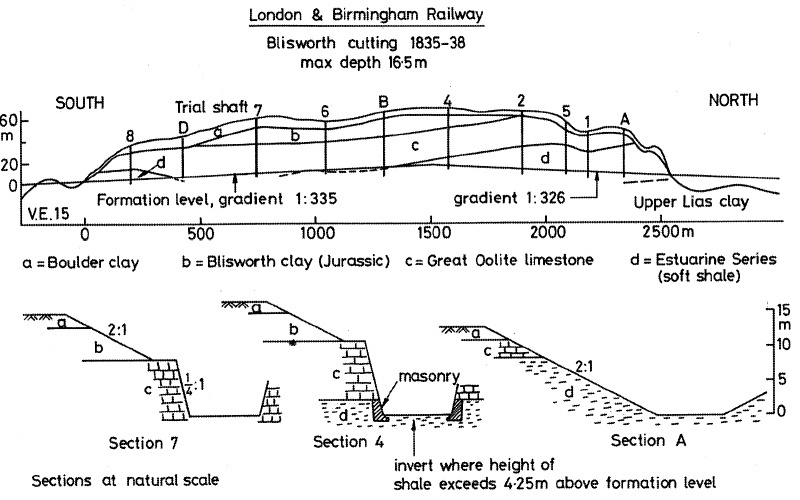
Section and
details of Blisworth Cutting, Prof. A. W. Skempton.
Drifts were also driven into the sides of the cutting behind the
retaining walls to drain off the water.
Some years later, in
addressing the House of Commons Select Committee on
Railway Labourers, Robert Rawlinson had this
to say about excavating the Blisworth Cutting (his are the answers):
Q. ― “A very severe cutting?”
A. ― “The heaviest open cutting, and largest work in its character,
excepting the Kilsby tunnel, on that railway.”
Q. ― “Were those works attended with a considerable loss of life?”
A. ― “There was a considerable loss of life, and very many accidents
upon the work; I kept no account of the number.”
Q. ― “In what way did those accidents occur?”
A. ― “At that cutting there was a top lift of from 10 to 12 feet of
gravel and clay, and marl of various consistencies; the bottom of a
portion of the cutting was composed of limestone rock, but a portion
of that rock at each end founded itself upon the clay again.
The top lift was taken off in the ordinary method of working
excavations, by means of wagons, and a great portion run out into
spoil by barrow runs. The bottom portion was cut off with
picks and wedges, and an immense quantity of gunpowder was used.
I believe as much as 100,000lbs in weight; the top portions of the
excavation was brought down at each end of the cutting by inclines
to the ordinary level of the railway, and those inclines were the
cause of considerable accidents from the temporary waggons; the men
would sometimes, through carelessness, put more waggons on the
incline than the brakesman could hold, and they would overcome him,
and sometimes a wheel would break, or a rail would get out of place.
I have seen as many as 20 waggons broken up at one time.
Frequently accidents would happen in this way: the men would get
upon these temporary waggons to ride from their work, and I believe
six or seven men had their arms and legs broken at one time, though
the contractor told them to get off the waggons at the top of the
incline, and they disobeyed him.”
Report from the Select Committee on Railway Labourers (1846).
After almost three years work on the cutting there remained
difficulties, especially with flooding. In his report to the
directors of February, 1838, Robert Stephenson describes how he
planned to expedite progress in extending the line from the
temporary terminus at Denbigh Hall to Roade, by forming the
embankment ― presumably that at Ashton ― using the technique known
as ‘side cutting’ [3]:
“The Blisworth Contract, which consists of
an extensive cutting is progressing favourably; but the character of
the excavation is now more difficult than at first, and as it gets
deeper, the space for employing men gradually becomes more confined.
The material is increasing in hardness, and there has also been a
greater quantity of water. In order to facilitate the
completion of this part of the line, an arrangement has been made
for throwing an additional quantity of earth into spoil from the
centre of the excavation, and supplying the deficiency in the
embankment by a corresponding quantity of side cutting at the
southern extremity of the contract. The object thus aimed at
is the completion of the south portion of the contract in May,
nearly at the same time with the Wolverton and Castlethorpe
contracts, at which period an extended opening may be made from
Denbigh-hall to the village of Roade, situate on the turnpike road
leading from Stony Stratford to Northampton, and only five miles
from the latter town. This position appears highly
advantageous for the next temporary terminus, which must remain the
terminus for the London division until the opening of the whole
railway.
In the Blisworth cutting there now remains
100,00 cubic yards of materials which will be disposed on nearly in
the following manner:―
30,000 cubic yards to Ashton Embankment;
35,000 cubic yards to Blisworth Embankment
35,000 cubic yards to spoil.
The first quantity is that which relates to the opening of the line
as far as Roade, and reckoning the south end of the cutting to yield
at the rate of 10,000 yards per month this may be effected in three
months, allowing necessary time for joining the permanent road.”
Robert
Stephenson’s Report, 17th February 1838. |
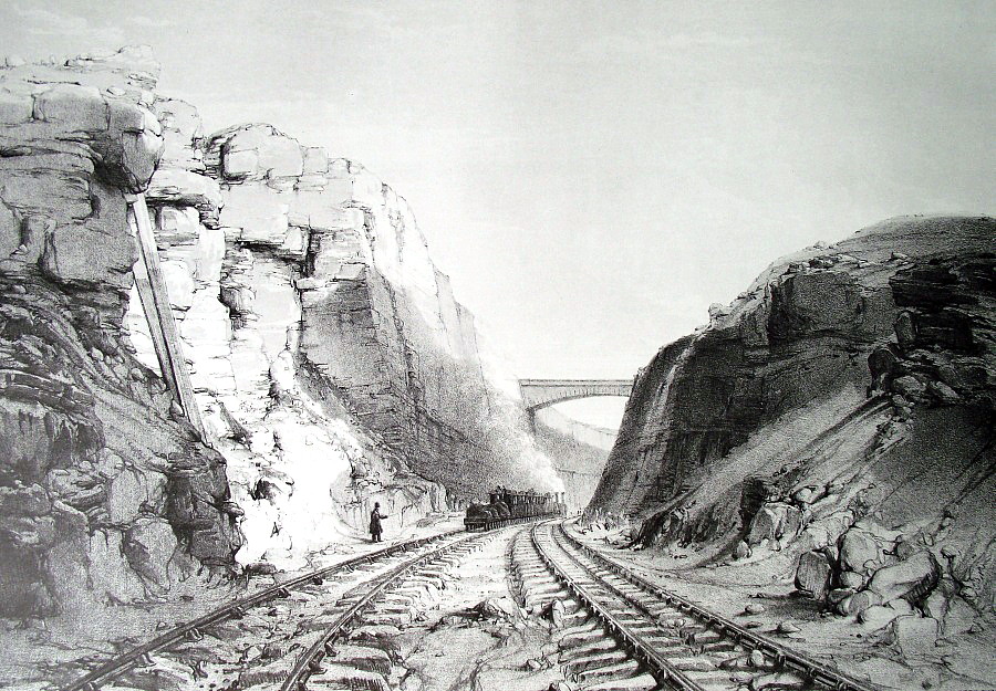
View in the deep cutting near
Blisworth, looking South, with a train passing.
John Cooke Bourne, October 1838.
|
Blisworth Cutting was eventually completed in August 1838, shortly
before the line was opened throughout, and Cooke Bourne was soon on
hand to produces two romanticised drawings of it. To the
extent that the artist’s hand and eye between them produced an
accurate depiction, his drawings contain several points of interest.
In the drawing above, note the top-hatted ‘policeman’ having given
the all clear to the southbound train, which is double-headed, not
unusual during the Edward Bury small-locomotive era. The
artist gives a good impression of what an exposed and isolated job
was a railway policeman’s lot. Note also the stone-block
sleepers, the very unfinished appearance of the trackbed by today’s
standards and, in both drawings, the rough and ready finish to the
stonework in the upper part of the cutting, which seems to be
inviting frost-induced rock fall.

View of the
cutting near Blisworth, looking North.
John Cooke Bourne, October 1838.
In the view looking north, note the change in the slope of the
embankment in front of the bridge. Presumably this is where
the stratum changes from limestone, which will stand vertically, to
clay/soft shale that has a lesser angle of repose.
Completion of the Blisworth Cutting did not end its civil
engineering problems ― clay continued to make its presence felt.
Shortly after the opening of the line, several slips occurred [4]
and over a decade later slippage remained a problem:

Parliamentary
Papers, House of Commons and Command, Volume 30.
In each case the solution was to build ‘counterforts’ ― in this
context, 5-feet wide trenches, dug at 20 feet intervals into the
slip (i.e. at right angles to the rails) and then filled with
well compacted gravel or crushed stone. The counterforts thus
divided the slip area into segments, acted as drainage channels, and
applied frictional force to the body of the clay to prevent it from
sliding forward.
――――♦――――
THE BLISWORTH EMBANKMENT
About a mile to the north of the Blisworth Cutting lies the
Blisworth Embankment, at the northern end of which the line crossed
the Grand Junction Canal on an iron bridge, the construction of
which was depicted by Samuel Brees:
|

Iron skew bridge over the Grand Junction Canal at
Blisworth under construction, by Samuel Brees.
See also
Appendix I.
|
“The
Railway intersects the Canal at an angle of 40º and at a point where
the height of the rails above the level of the water is 29 feet 8
inches, and the depth of the Embankment 25 feet. The Railway
rises in the direction of Birmingham at the rate of 1 in 330.
The Bridge will consist of six Main Ribs of cast iron, forming an
arch of 66 feet span on the skew, and 11 feet 9 inches rise, and
leaving a clear width of 33 feet 6 inches between the abutments,
measured at right angles, to the centre line of the canal.
Each of the Ribs will consist of three pieces, upon which the open
work of the spandrels will be fixed. Beams of Oak will run
along the top of the four middle ribs, and be bolted to them; to
these beams will be attached the Railway Chairs. The spaces
between the ribs will be covered with cast iron Plates, upon which
the ballasting of the Railway will be laid.”
An extract from the specification for
the Blisworth canal bridge,
reproduced in Railway Practice
(1838 edition) by S. C. Brees.
In common with the neighbouring cutting, the Blisworth
Embankment also proved problematic. As Robert Rawlinson,
contractor for the work, explained in evidence to a Parliamentary
select committee, the plastic nature of the material from which the
embankment was formed caused frequent slippage during construction:
Q. ― “The last witness mentioned just now that there had been some
accidents at the ‘tips’; can you explain the nature of the ‘tip’?”
A. ― “I will try to do so. The ‘tip’ is the place where the
material is teemed over to form the embankment; the tip is a
removable point in a long embankment; the extreme end of the
embankment; and in a heavy embankment, such as the Blisworth, at
least 40 or 50 feet in height, it was a most difficult operation,
with the material they had to work, to keep these ‘tips’ at their
ordinary level. To do so they were constantly obliged to raise
the levels, and run up hill a portion of the time; but supposing
they had got the ‘tip’ 10 feet high in the morning, perhaps tomorrow
morning they would find it 15 feet below the proper level.”
Q. ― “The material would have sunk?”
A. ― “Subsided or slurred out at the sides.”
Evidence give by
Robert Rawlinson to the Select Committee on Railway Labourers, 1846.
Nevertheless, it still came as a surprise when a
phenomenon ― later to become known as ‘delayed embankment failure’ ―
occurred two years after the Railway had opened for service:
“Saturday
evening a considerable subsidence took place at the Blisworth
embankment, half way between the station and the bridge over the
canal. The earth having become thoroughly saturated by the
late rains, gave way at the bottom, and the surface in consequence
gradually sunk, at one point several feet. Since then it has
continued to subside at the rate of about a foot an hour, and on one
occasion between two and six in the morning, when the men ceased to
work, it sank eight feet. A large force of men were collected
the moment the slip was discovered, and employed day and night
replacing the soil that had given way with ballast, the trains in
the mean time passing slowly over the spot. The gap is always
filled up by the arrival of a train, and the precautions taken are
such as to do away with all idea of danger. The ballast is
brought partly from Bugbrook, but chiefly from Hillmorton about 16
miles distant.”
Northampton
Mercury, 11th January 1840.
Delayed failure is yet another aspect of risk in clay formations,
and one that continues to affect railway embankments:
“Cyclic
shrinking and swelling of clay earthworks causes a major maintenance
headache for UK asset managers. Millions of pounds are spent
each year to realign and tamp sections of track twisted by
embankment movement, a problem compounded by vegetation that
increases clay shrinkage in the summer. Vegetation removal
could ease the problem, however, it could also increase the risk of
slope instability . . . . The type of soil and vegetation were
also important in controlling the water content within embankments.
High plasticity soils such as London Clay have a greater swelling
capacity and take up more water during wet periods . . . . The
shrinking and swelling movement is thought to result in progressive
embankment failure. Strain softening at the toe results in
deformation retrogressing back into the embankment, resulting in a
deep-seated failure.”
New Civil Engineer, 4th
August 2008.
――――♦――――
A VERY UNUSUAL RAILWAY BRIDGE
In two of the contemporary railway guides, there are descriptions of
a very unusual bridge that the line once crossed in its northbound
approach to Weedon Station:
“This part of the road is, perhaps, more
curious than any along which we have hitherto passed. A branch
of the [Grand Junction] canal,
which is carried to the storehouse of the depot, is here crossed
by a strong draw bridge, over which we rattle fearlessly and
merrily, and, passing by the long dead wall of the barrack grounds
on our left, we arrive at the Weedon Station.”
The London and
Birmingham Railway Guide, Joseph W. Wyld (1838).
“The village, however, is chiefly
interesting to the stranger on account of its Royal Military Depot.
This magnificent establishment, which is supposed to be equal to any
of the kind in Europe, consists of a handsome centre and two
detached wings, and is capable of containing 240,000 stand of small
arms, with a proportionate quantity of artillery and ammunition.
The barracks, in which troops are continually kept for the
protection of the place, stand on the top of the hill, and are
intended to accommodate 500 men. A cut made from the Grand
Junction Canal to the magazines, for facilitating the conveyance of
stores, gave considerable trouble to the engineers of the railway,
by its having to be crossed at a height very little above its own
level. This object was, however, at last effected by means
of a drawbridge, of peculiar construction and extraordinary strength.”
Drake’s Road
Book of the London and Birmingham Railway, James Drake (1839).
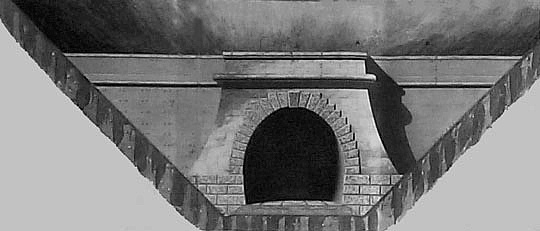
|
 |
|
Royal
Military Depot service canal and portcullis, Weedon. |
The Royal Military Depot ― now the
decaying remnant of an architectural gem ― is a relic of the
Napoleonic Wars. Built during the first years of the
nineteenth century, the Depot was probably sited at Weedon to be
well away from potential invasion shores, but with good
communications to other parts of the country via the Grand Junction
Canal. Indeed, the Depot was linked to the Canal by a short
spur, which entered the (then) walled area through a portcullis,
before passing between its two imposing rows of warehouses/armouries
to a turning basin at the far end of the site.
The route taken by the Railway passed along the Depot’s
eastern boundary, crossing the branch canal ― as Drake relates ― “at
a height very little above its own level.” Understandably,
the Military did not wish their branch canal to be obstructed by the
Railway, so Stephenson came up with an unusual solution, a
drawbridge, not of the lifting variety but one that could be pulled
back horizontally to permit canal barges to enter the Depot.
To ensure that the Railway Company delivered their end of the
bargain, the details relating to the drawbridge and its operation
were included in the second London and Birmingham Railway Act:
“LXXXII. And be it further enacted,
That the said Company shall, at their own Costs and Charges,
construct a Drawbridge in that Portion of the said Railway which is
to pass over the said Basin of the Ordnance Canal, for the Purpose
of affording a free Passage for the Boats and other Craft of the
Ordnance Department into and out of the said Canal; and shall and
will at all Times thereafter, and at the like Costs and Charges,
provide and maintain a proper Person to be always in attendance at
the said Drawbridge, who shall without Delay open the same whenever
he shall be so required by any Ordnance Officer, Boatman, or
Servant, that the Boats and other Craft belonging to or hired by the
Department may pass into and out of the said Canal.”
William IV,
Cap lvi, R.A. 3rd July 1835.
A description of the bridge and its operation together with part of
the drawings are reproduced at Appendix II.
――――♦――――
THE KILSBY TUNNEL
“We now
proceed for rather more than half a mile, when we arrive at the KILSBY
TUNNEL. This astonishing memorial of the
power of mind over matter, was accomplished only by the most
persevering exertion combined with engineering skill, and presented
constant and unexpected difficulties, which were continually
demanding the promptest exertion of the engineer’s resources.”
Freeling’s
Railway Companion, from London to Birmingham, Arthur Freeling
(1838).
The Primrose Hill Tunnel, the Tring Cutting and the Wolverton
Embankment might be considered to share one level of civil
engineering difficulty, with the Blisworth Cutting on the next level
above. But the crowning challenge faced by Stephenson and his
team was to drive the railway tunnel through the Kilsby Ridge, a
feat that must rank among the great civil engineering achievements
of the railway building era:
“Another instance, in which difficulties of
no ordinary magnitude were encountered, was at the Kilsby Tunnel,
about six miles on the London side of Rugby station. This
tunnel is about 2,400 yards long, and was originally intended to be
chiefly built [the brick lining]
eighteen inches thick; but it was found necessary to increase this,
in most cases, to twenty-seven inches; and the whole has been built
in either Roman or metallic cement. The works were commenced
about the middle of June, 1835, by J. Nowell and Sons, contractors;
but such serious difficulties were met with, at an early stage of
the proceedings, that they gave up their contract on the 12th March,
1836, and nearly the whole had to be performed by the Railway
Company.”
The History of
the Railway Connecting London and Birmingham, Lieut. Peter
Lecount R.N. (1839).
The Kilsby Tunnel lies near to the ‘Watford Gap’ in
Northamptonshire. As its name suggests, the Gap marks a
low-lying point on a range of high ground, similar to the Tring Gap
through which the line crosses the Chilterns further south. In
this case the high ground is a limestone ridge that runs in a
south-westerly to north-easterly direction, from the Cotswolds to
the Lincolnshire Wolds, and although not of particular prominence,
it forms an obstacle to transport communications. Since Roman
times, civil engineers have found the Watford Gap a convenient route
for connecting the Midlands with the South East ― the A5 (the Roman
Watling Street), the West Coast Main Line (formerly the London and
Birmingham Railway), the M1 motorway and the Leicester Line of the
Grand Union Canal traverse the Gap in parallel within its width, a
mere 1,300 feet.

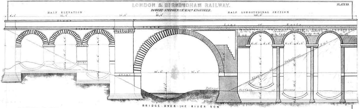
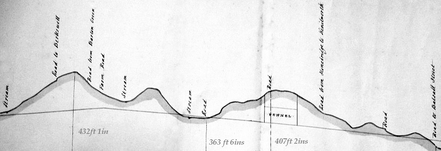
An extract from Stephenson’s
sectional drawing of the line, showing the Kilsby Tunnel.
The two marked heights above datum
indicate the line’s depth below the ridge.
There is no hard and fast rule, but a point is reached at about 60
feet below surface level at which it becomes more economical to
drive a tunnel than to excavate a cutting (taking into account the
cost of land, labour, and the disposal of excavated material where
this is necessary). [5] In order to
maintain the line’s ruling gradient (1:330), Stephenson was able to
take the Railway over the ridge of the Chilterns (at Tring) in a
cutting of average depth 40 feet (maximum 60 feet), but at Kilsby
the line needed to traverse the summit at a much greater depth,
hence a tunnel was necessary.
Previous tunnelling in the area had exposed the risk of quicksand.
During the 1790s, Barnes and Jessop had encountered a 328-yard
deposit of quicksand while driving the Braunston canal tunnel
through high ground to the north of Daventry (some 3½-miles south of
Kilsby). Some 20 years later, Benjamin Bevan encountered
quicksand at Crick, 1½-miles east of Kilsby, while building the
‘old’ Grand Union Canal; the problem was sufficient to cause him to
abandon his original line to the west of Crick Village and take a
route (and a longer tunnel) on its eastern side. [6]
During a visit that Stephenson paid to Dr. Arnold, the famous head
master of Rugby School, he received a salient warning, probably
based on Arnold’s knowledge of the canal builders’ experiences:
“On his first visit to Rugby after the Bill
for the London and Birmingham Railway had received the Royal assent,
Robert Stephenson called on the great schoolmaster to offer him his
respects. The young man brought no letter of introduction, and
either was, or imagined himself to be, received with coldness and
hauteur. Dr. Arnold was certainly polite, but perhaps formal,
his manners being of a school with which, at that period of his
life, Robert Stephenson was not familiar. Anyhow the interview
left on the mind of the engineer an unpleasant impression, which was
doubtless in some part due to Arnold’s last words: ‘Well, sir,’
he said, pointing in the direction of the Kilsby ridge, ‘I
understand you carry your line through those hills. I confess
I shall be much surprised if they do not give you some trouble.’
In due course the trouble came.”
The Life of
Robert Stephenson, F. R. S., J. C. Jeaffreson (1864).
Building the tunnel commenced in the usual manner. Bore holes
sunk along a line to the east of the existing tunnel caused it to be
abandoned when they revealed the presence of quicksand. Bore
holes were then sunk along a more westerly line; these revealed
various clays, some gravel and limestone and, in some, a
considerable quantity of water, but no quicksand.
Excavations were then commenced by the contractor, Joseph Nowell &
Sons, whose family had also taken the Harrow contract. A
number of
working shafts were sunk along
the line of the tunnel, from the base of which working faces could
then be opened in both directions. However, a shaft sunk near
to the tunnel’s southern end encountered what Lecount, presumably
referring to its high fluid content, described as “a perfect
quicksand”. Further exploration established that one of
the trial bore holes had only just missed the deposit, which further
testing revealed to be considerable and extending down below rail
level. The deposit’s extent precluded tunnelling on a
different alignment.
The working shafts sunk in the central and northern sections of the
line were dry, and excavation was commenced from those points, but
the shaft sunk some 500 yards from the southern portal encountered
the quicksand. Driftways run into the quicksand to drain it
became blocked with sand, so Stephenson resorted to steam pumping,
probably the first occasion that approach had been used on any scale
in civil engineering work. Initially, two steam powered pumps
were erected and shafts sunk to allow pumping to take place.
This met with moderate success at first, but was suddenly reversed
by renewed and serious flooding:
“Mr. Stephenson was led to suppose that the
water might be pumped out, and that under the sand thus drained the
tunnel might be driven with comparative facility; this proved to be
the case, but the expense was of course enormous. Engines for
pumping were erected, and shafts sunk a little distance out of line
of the tunnel. These shafts were carried through the sand by
means of wooden tubbing, and from them, headings were driven into
the quicksand to allow the water to flow with freedom to the pumps.
The pumping was contained nearly nine months before the sand was
sufficiently dry to admit to tunnelling, and during a considerable
portion of that time the water pumped out was two thousand gallons
per minute.”
The History of
the Railway Connecting London and Birmingham, Lieut. Peter
Lecount R.N. (1839).
In the meantime Joseph Nowell fell ill and died. Although his
sons continued the contract for a time, they eventually gave up and
the work was returned to the Company, Stephenson placing it under
the supervision of Charles Lean, a sub-assistant engineer of whom
Samuel Smiles relates the following anecdote:
“The tunnel, thirty feet high by thirty feet broad, arched at the
top as well as the bottom, was formed of bricks laid in cement, and
the bricklayers were progressing in ‘lengths’ averaging twelve feet,
when those who were nearest the quicksand, on driving into the roof,
were suddenly almost overwhelmed by a deluge of water which burst in
upon them. [this happened in November 1836]
As it was evident that no time was to be lost, a gang of workmen,
protected by the extreme power of the engines, were, with their
materials, placed on a raft; and while, with the utmost celerity,
they were completing the walls of that short length, the water, in
spite of every effort to keep it down, rose with such rapidity that,
at the conclusion of the work, the men were so near being jammed
against the roof, that the assistant engineer Mr. Charles Lean, in
charge of the party, jumped overboard, and then swimming with a rope
in his mouth, he towed the raft to the foot of the nearest working
shaft, through which he and his men were safely lifted up into
daylight, or, as it is termed by miners, ‘to grass’. The water
now rose in the shaft, and as it is called, ‘drowned out’ the
works.”
The Life
of George Stephenson and of his son Robert Stephenson,
Samuel Smiles (1862). |
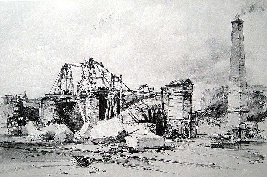
Above: Head-gear and Engine at great
Ventilating Shaft, employed in raising Earth, &c., from the Tunnel
during its construction.
Below: Pumps for draining the
Kilsby Tunnel.
By John Cooke Bourne, July 1837.

|
Further steam pumps were erected to counter this renewed flooding,
more pumping shafts were sunk down to trackbed level, and headings
were then driven to connect them with the working shafts. By
these means, the water was gradually drained out of the workings.
And to claw back lost time, Stephenson also sank further working
shafts to permit additional faces to be opened up. At the
Company’s 9th General Meeting in February 1838, he was able to
report that . . . .
“The works of the Kilsby Tunnel are at
present in a very satisfactory state, and the monthly progress as
regular as can be expected considering the nature of the operations.
No new difficulty has recently occurred, except the capricious
appearance and disappearance of water in some of the shafts both in
and beyond the quicksand. Between these shafts the junction of
the respective portions of the tunnel has consequently become rather
uncertain, the actual rate of progress in tunnelling through the
intermediate space falling short of what was estimated. To
remove this source of contingency as much as practicable it has been
found necessary to sink additional shafts for the purpose of
dividing those unfinished portions which would require the longest
time to execute, or in which the average rate of progress was most
likely to be interrupted by water or a change in the nature of the
strata. On the 20th of January last, a careful admeasurement
was made to determine accurately the distance unfinished between
each pair of shafts, and the time of completion for each calculated
upon an average which there are the no reasonable grounds for
doubting. From which it appears that the whole tunnel will be
completed by the end of next July. In the quicksand,
especially, although effectually drained, the utmost caution in
mining has been required, and an expenditure of timber unavoidably
incurred, which would appear excessive and lavish to any one whose
experience has been confined to ordinary tunnelling. Several
circumstances have occurred demonstrating that none of the
precautions or expenses have exceeded what the magnitude of the
difficulties attending this work imperatively demanded.”
Extract from
Stephenson’s report to the 9th General Meeting: Mechanics’
Magazine, p.399, Vol. XXVIII. (1838).
Work was eventually completed in June 1838 at a cost of £320,000,
£221,000 above the contract price. Charles Lean layed the
final brick with a silver trowel: [7]
“By the main strength of 1250 men, 200 horses, and thirteen steam
engines, not only was the work gradually completed, but during night
and day, for eight months the astonishing and almost incredible
quantity of 1800 gallons per minute from the quicksand alone was
raised by Mr Robert Stephenson, and conducted away!”
The Life of
George Stephenson and of his son Robert Stephenson, Samuel
Smiles (1862).
. . . . to which Stephenson’s other early biographer,
Jeaffreson, [8]
added further information (the number of bricks referred to should,
perhaps, be taken as a general indication of scale, rather than of
factual accuracy):
“A few facts briefly stated, will enable the reader to form some
conception of the labour expended upon it. Thirty-six millions
of bricks were used in its construction. The two shafts by
which it is ventilated and supplied with light are sixty feet in
diameter, and the deeper of them contains above a million of bricks.
These two enormous shafts the walls of which are perpendicular, were
built from the top downwards, small portions of the wall (from six
to twelve feet long and ten feet deep) being excavated at a time,
and then bricked up with three feet depth of bricks, laid with Roman
cement. At one time 1,250 labourers were employed in building
the tunnel. To lodge and cater for this army of navvies, a
town of petty dealers soon sprung up; sheds of rude and unstable
construction rose on the hill above the tunnel, and in them a navvy
could obtain at a high rent the sixteenth part of a bed-room.
Frequently one room containing four beds was occupied by eight day
and eight night workmen, who slept two in a bed, and shifted their
tenancies like the heroes of a well known farce.”
The Life of
Robert Stephenson, F.R.S., J. C. Jeaffreson (1864). |
|
 |
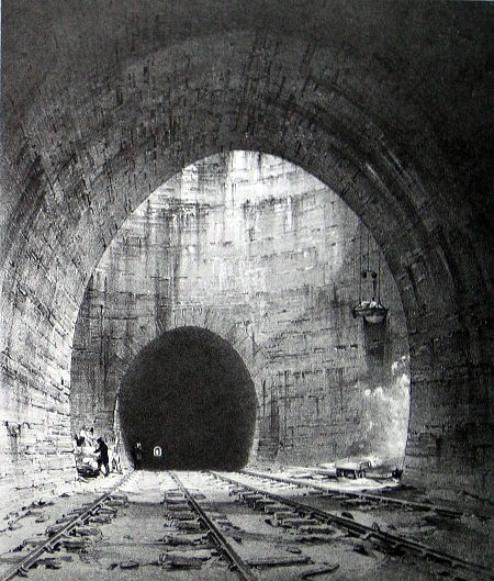 |
|
Kilsby Tunnel.―Interior view, under a
working shaft.
John Cook Bourne, July
1837. |
Kilsby Tunnel.―Interior view, under
one of the great Ventilating Shafts.
John Cook Bourne, October
1838. |
|
“In May, 1836, one of
the large ventilating shafts was commenced, and completed in about
twelve months. This shaft is sixty feet in diameter in the
clear, and 132 feet deep; the walls are perpendicular, and three
feet thick throughout, the bricks being laid in Roman cement.
The second ventilating shaft is not so deep by thirty feet.
These immense shafts were all built from the top downwards, by
excavating for small portions of the wall at a time, from six to
twelve feet in length, and ten feet deep.”
The History of
the Railway Connecting London and Birmingham, Lieut. Peter
Lecount R.N. (1839). |
|
 |
|
View from above Kilsby Tunnel,
looking towards Rugby.
John Cook Bourne, July 1837.
The railway on which the two figures
are standing was built to assist engineering work.

Above: northern portal, Kilsby
Tunnel.
Below: elevation of Kilsby Tunnel
reproduced in Railway Practice by S. C. Brees (1847 edition). |

――――♦――――
|
CONSTRUCTION IN WARWICKSHIRE
A short distance to the north of the Kilsby Tunnel, the Railway
enters Warwickshire and for the next dozen miles descends gently
into the valley of the River Avon, which it crosses near Wolston.
From Kilsby onwards to Birmingham there were no further significant
civil engineering challenges, although that is not to say that
construction was devoid of difficulty . . . .
“Another troublesome and expensive part of
the line was the Coventry contract. This did not arise through
any peculiar difficulty in the nature of the work, but from the
supiness and incapacity of the contractor. The work went on
without spirit or energy, and the time was rapidly going by which
would enable it to be completed with the other parts of the line at
the end; the opening of the railway would hence be delayed, and it
was difficult to foresee all the consequences. In this dilemma
the Company could do nothing but take the work into their own hands;
and by great exertions, and a corresponding outlay, it was completed
in time.”
The History of
the Railway Connecting London and Birmingham, Lieut. Peter
LeCount R.N. (1839).
. . . . nor of interest; indeed, Cook Bourne’s romantic vistas
illustrate how well Stephenson’s creations once blended into ―
indeed, complemented ― what was then a rural landscape. |

West side of the Viaduct over
the River Avon, near Wolston,
by John Cooke Bourne
|
“This viaduct, of which the total length is
about 350 feet, consists of nine semi-elliptical arches, 24 feet
span, and 7 ft. 6 in. rise, and three semicircular arches at each
end, of 10 feet span, faced entirely with stone. Each of the
six end arches has a brick inverted arch between the piers above the
foundations, which are carried along uniformly in a solid bed
beneath these arches, with such steps and at such levels as the
nature of the substratum required. The three middle arches
have an inverted arch of brick-work, which forms an artificial
channel for the river. This invert is faced at each end with a
row of sheet piling, driven through the loam into a bed of strong
gravel beneath. All the foundations which do not reach this
gravel are built upon thick beds of concrete, and a layer of the
same material covers the whole of the arches, forming a level bed
for the gravel in which the sleepers of the railway are laid.”
The Practical
Railway Engineer, George Drysdale Dempsey (1855).
Bourne’s view of the Avon depicts a magnificent structure striding
across the river valley, its central arch mirrored in the water.
Sadly, this view of the Wolston Viaduct is now partly obscured by
foliage, while some of the its secondary arches have been bricked in
and the embankment extended. The top dressing of high tension
paraphernalia further detracts from what remains on view, but such
is the cost of progress. |

Above and below: drawing showing
elevation of the Avon (Wolston) Viaduct ― note the invert under the
central arches.
Reproduced in The Practical
Railway Engineer, George Drysdale Dempsey (1855).

View near Coventry.
The Sherborne Viaduct,
by John Cooke Bourne,
June 1839.
Stephenson used the same design for the nearby Sowe Viaduct, see
below.
Stephenson’s
drawing of the Sowe Viaduct near Coventry.
|
From the Avon Valley, the line commences a 10-mile ascent to
traverse the final summit on its journey to Curzon Street.. The
authors of contemporary railway guides generally name this the
Meriden Ridge, although the deep cutting and tunnel that carry the
line over the ridge is much nearer Reeves Green, a name also used on
occasions:
“The valley of the river Avon forms one of
the basins, or lowest points to be passed as has been
before explained, and
the intersection of high ground between it and Birmingham, called
the Meriden ridge, one of the summits. On the present line the
rate of inclination between the Avon and Meriden ridge is sixteen
feet per mile only. Now on the direct line the Meriden ridge
must have been crossed as well as in the present line, but in a less
advantageous place; inasmuch as the river Avon near Warwick is very
considerably lower than at Wolston, where it is now crossed, and the
Meriden ridge would have been intersected at a higher point than at
present, besides the circumstance of these high and low points being
much nearer together.”
The London and
Birmingham Railway, Thomas Roscoe and Peter Lecount (1839).
Regardless of the topography, Roscoe and Lecount neglect the
commercial advantages of taking the line through the growing
industrial areas of Rugby and Coventry.
It was originally planned to take the line over the Meriden Ridge in
a cutting. Perhaps the terrain, mainly sandstone, suggested
tunnelling to be the more economic solution, but whatever the reason
the resulting Beechwood Tunnel is the sole example of its type
between Kilsby and Birmingham. |
Above: the section of the Railway
over the Meriden Ridge showing the position of the Beechwood Tunnel.
Below: the Beechwood Tunnel (note ‘railway policeman’ in the
foreground ― what an awful job that must have been!).

|
Stephenson’s judicious use of stone in the single-span bridge
fronting the Beechwood tunnel, and in the tunnel entrance, caused
the architectural critic Henry Noel Humphreys to wax lyrical:
“POLYCHROMY ― Across
the Beechwood excavation through this solid rock, where upwards of
193,766 cubic yards of stone have been removed, is thrown one of the
most beautiful structures of the whole line. It consists of a
single arch of 76ft span, springing from the natural abutment of the
naked rock, to which it is cemented, as it were, by a bold but
simple moulding; and the arch being of the same stone as the rock
produces a beautiful mingling of art and nature, which is most
agreeable to the eye. We now enter the Beechwood tunnel, and
here meet with another fine piece of architecture in the entrance.
It is in the Egyptian style, the cumbrous proportions of which seem
well fitted for such a purpose, particularly in the manner of their
adoption in this design, which is simple and good; though, perhaps,
the boldness of the string courses have been a little exaggerated,
the lower one having a projection of 2ft 9in. But this
entrance is more interesting in another point of view, I mean on
account of the introduction of a polychromic effect, produced in
what I conceive a more legitimate way than by the use of artificial
colour; by the employment of materials of various natural colours;
the string courses and copings being of a fine bluish grey stone (I
should imagine from the Roade excavation), whilst the mass of the
structure is of the red stone found upon the spot. The effect
produced is varied and agreeable, and the two colours contrast
exceedingly well; the effect, indeed, is such, that I feel convinced
that, if this method were pursued upon principles of pure taste, so
as to vary the effect of a building without rendering it patchy, and
to call in colour judiciously to the aid of form, we should soon
come to consider a great building all of one colour as monotonous,
and entirely wanting in one of the great elements of pictorial
effect.”
The
Architectural Magazine, Volume 5 (1838).
It seems that the excavation was not, as the previous commentator
states, entirely through “solid rock”, for part of the tunnel
required a brick lining, which was soon in need of major repair:
“The tunnel is built of brick, is 302 yards
long and passes through strata consisting of alternate layers of
rock and marle, [9]
abounding in springs water; it was
completed at the latter end of the year 1837; that winter being of
unusual severity, many of the bricks were partially destroyed owing
to their containing lime, upon which the weather acted. Mr.
Robert Stephenson first contemplated applying a coat of cement
throughout the inside of the arch, but it was apprehended that it
would not adhere, in consequence of the constant dripping of the
water. No positive steps were, however, taken until the
effects of the winter of 1839-40 had so injured the brickwork as to
render further delay dangerous; it was then resolved to line the
whole length of the tunnel with an interior brick arch, 9 inches
thick, so as to support and insure the stability of the old work . .
. .
. . . . The whole of the work was done with blue hard burnt
Staffordshire bricks, laid in cement and sand, in equal proportions,
for the side walls; for the arch, up to within 15 inches of each
side of the crown, two-thirds of cement, and one third of sand; the
two rings for keying up the centre or crown were laid entirely in
cement, without any mixture of sand. Previous to commencing
the new work, a series of chases [10]
were made in the old wall, which, when closed in front by the lining
arch, formed drains, 4½ inches square, terminating in the culvert
beneath the centre of the railway, and conveying thither all the
water, which would otherwise have separated the new from the old
brickwork. This work was finished, and the scaffolding
removed, within the short space of forty days, by Messrs. Grissell
and Peto, under the direction of Mr. Robert Stephenson, and the
immediate superintendence of Mr. Dockray.”
The Civil
Engineer and Architect’s Journal, Volume 4 (1841).
To the east of Hampton in Arden lies the next point of interest on
the line, the viaduct over the River Blythe, the drawing of which by
John Cooke Bourne has been particularly admired. It . . .
“. . . . consists of two bold arches, each
of fifty feet span, separated from the abutments by pilasters of ten
feet in width; the whole length of the parapet being 132 feet.
Mr. Bourne’s drawing of this viaduct is, probably, the most poetical
in the series; it is a scene of new-born art and picturesque decay;
the fresh and substantial Railway Viaduct, contrasting forcibly as
Mr. Britton observes, ‘with the old and ruined footbridge over the
same stream, a few yards below.’ Here, indeed, are ‘sermons in
stones:’ thousands dart along the new structure quickly as the sand
of life runs out; years may roll on, and the viaduct be deserted, as
the foot-bridge is now, for some new triumph of ingenuity; whilst
the river flows on softly beneath both structures . . . .”
The Literary
World, Volume 2 (1840). |
West side of Viaduct over the
River Blythe.
John Cooke Bourne, October 1838.
|
.JPG) |
|
.JPG) |
.JPG) |
.JPG)
The Railway’s Birmingham terminus at Curzon Street Station, the
remains of which are pictured above, is covered in
Chapter 11. |
|
CHAPTER
9
――――♦――――
APPENDIX I.
IRON BRIDGES
from
The Encyclopaedia Britannica, Vol. 12 (1856).
The iron
segmental skew arch bridge across the Grand Junction Canal at Nash
Mill.
The requirements of railway practice have by no means been
favourable for the introduction of the iron arch the height
required, from the circumstance that the roadway must be over the
top, the practical difficulty of meeting the thrust, and the
necessity of a perfect stability in its foundations, have all been
drawbacks to its use, although some of our most elegant and
efficient railway bridges are cast iron arches.
The earliest examples we have of such an application of cast iron
arches are in a series of three bridges for crossing the London and
Birmingham Railway over the Grand Junction Canal at
Blisworth, Boxmoor, and Nash mill [above].
That at Blisworth is of 50 feet clear span, and consists of six
cast-iron arched ribs, having a rise of 8 feet; the four inner ones
are arranged in two pairs, one under each line of rails; the two
ribs composing each pair being 4 feet 11 inches from centre to
centre, and a 6-feet space between each pair; the two single outer
ribs are again 6 feet from those in pairs; making a total width from
centre to centre of the outer ribs of 27 feet 10 inches. The
depth of the ribs is 2 feet 3 inches at the springing, diminishing
to 2 feet at the crown; their thickness is 2 inches, with a
projecting flange 6 inches wide at the top and bottom; making a
total sectional area of 51 square inches in each rib at the crown.
They rest on cast-iron skew back plates, and these again on blocks
of stone let into the brick piers. The ribs are each made in
three equal segments bolted together, and are connected by a system
of trussing which we shall hereafter describe. The haunches
are filled in with three separate castings, one over each spandril,
and one as a saddle over the crown. The pattern consists of
bars of a cruciform section, crossing each other diagonally, and
forming diamond-shaped panels, decreasing in size towards the crown,
whose upper apices are connected together by a rib or top table, and
their lower ones connected to the main rib by being keyed in between
projections upon it. Upon the top tables just mentioned, and
firmly bolted to them, are placed strong cast-iron plates 3 feet
wide, ¾th of an inch thick, with flanges 4¾ inches deep all round,
and diagonal flanges from corner to corner. These answer the
double purpose of steadying and bracing together the spandrils, and
also of carrying the ballast, which, however, is not used for
bedding sleepers, the rails being carried in chairs resting on
longitudinal balks of timber, and bolted down through them to the
top table of the spandrils.
The peculiar feature of the bridge is in the system of trussing
employed to connect the main ribs. At equal distances along
the curved rib there are cast iron struts furnished with skew ends,
with bevelled edges, for the purpose of keying them in between
projections cast on the main ribs; these struts are 12 inches deep,
2 inches thick, and all radiate towards a line joining the centres
of curvature of all the arched ribs. The skew end of one strut
is placed opposite that of the strut on the other side of the rib,
so that they form a zig-zag line, the general direction of which is
parallel to the abutments; between these struts are placed distance
pieces of a cruciform section, with broad ends with bevelled edges,
and keyed in between projections on the struts in the same manner as
the latter are fixed to main ribs. The skew-back plates before
mentioned the whole length of the abutment, and are of an irregular
shape, so as both to fit the springing of the arch, and to radiate
in the same manner as the struts above mentioned, forming, indeed,
the last of these struts on each side.
It will be observed that the whole of the bearing portion of this
bridge is put together without any bolts (with the exception of
those at the junctions in the main ribs, and those fastening the
platform plates to the top tables of the spandrils), every junction
being made with keys in the manner just described, so as to render
motion in the almost impossible, and to assimilate the system, as it
were, to one entire piece.
The bridge, indeed, though not perhaps remarkable for its great
span, is one that justly deserves notice for the extreme care
bestowed by the designer on the minutiae of all its parts, and the
great rigidity given to it by the system of trussing so well adapted
to the purpose.
The bridge over the canal at Boxmoor is of much the same
description; the arrangement of the ribs is precisely the same as of
those at Blisworth, but the span and rise are greater; the former is
66 feet, and the latter 11 feet 9 inches, the depth being 2 feet 9
inches at the springing, diminishing to 2 feet at the crown; the
spandrils are similar to those at Blisworth, and also the top
plates, except that they are lozenge shaped instead of square.
The trussing of the main ribs is different, the system of keying not
being so entirely adhered to. It consists of cast-iron struts
of a cruciform section keyed in between the main ribs in lines
perpendicular to the abutments, and of cast-iron pipe struts,
through the entire length of which wrought-iron tie-rods pass, and
which extend from side to side of the bridge parallel to the
abutments. These also are keyed in between the main ribs, but
are not in any way connected with the struts described as being
placed at right angles to the abutments.
The bridge at Nash-mill is precisely similar to the one at Boxmoor.
The outer ribs of these bridges are surmounted by light cast-iron
railing which extends some distance each way past the arch to the
top of the slopes on either side, and gives the bridge a neat and
pleasing appearance.
――――♦――――
APPENDIX II.
Description of a Drawbridge on the London and Birmingham
Railway,
at Weedon. By CAPTAIN JEBB,
Royal Engineers.
From
PAPERS ON SUBJECTS CONNECTED
WITH THE DUTIES
OF THE
CORPS OF ROYAL ENGINEERS.
Vol. III, 1839.
The London and Birmingham Railroad crosses a branch canal at Weedon,
which communicates between the Grand Junction Canal and the
extensive storehouses and magazines belonging to the Ordnance
Department at this station. As it was provided in the Act of
Parliament that a drawbridge should be placed over this branch
canal, in order that the water communication might be preserved, Mr.
Stephenson, the chief engineer, designed a bridge for this purpose,
which having been submitted for the approval of the Master-General
and Board of Ordnance, was sanctioned by them, and has been recently
completed.
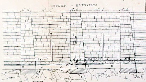
Plate 26 will serve to explain the principle upon which the bridge
is constructed, and the mode in which it is adjusted in its place as
a portion of the line of railway, and removed, when necessary, for
the passage of boats.
Fig 1, is a horizontal section through the middle of the main frame,
showing a plan of the line of railway and the canal, with the bridge
in its place; ABCD is a cast iron frame, which carries the chairs
for the rails. This, when in its place, is supported at the
angles by four large screws, l, m, n, o, and, when a passage along
the canal is required for boats, is removable upon the three wheels,
E, F, G, which work on two rails, HI and JK, fixed on the solid
walls, which appear below, at an angle of 45º with the line of the
railroad. Such weights as may be necessary for adjusting the
centre of gravity of this mass, so that when in motion it may rest
fairly on the three wheels, are placed on the broad flanges in the
line CD and about the wheel G.

Part of the
drawing for Stephenson’s railway drawbridge at Weedon.
The platform of the bridge is covered with cast iron plates, bolted
down upon the main beams by ½-inch bolts. These beams are
placed at the same distance apart as the rails on the line of road,
and chairs bolted down to them with ⅞-inch bolts serve to support
the line of rails across the bridge: both the chairs and the plates
have a thickness of patent felt between them and the main beams.
It will be obvious that the proposed object of removing the bridge
is effected by rolling it bodily out of the way on the lateral
rails, laid at an angle of 45º, until the passage of the branch
canal is clear. The force necessary for this purpose has
hitherto been applied in a very simple manner, by inserting iron
crow-bars into the holes shown in the circumference of the wheels:
this mode, however, is tedious, and as expedition is an object under
the circumstances, an apparatus, the nature of which will be
understood by referring to the explanatory sketches, figs. 4 and 5,
is to be placed in the vacant space PP under the bridge, by which
its removal will be accomplished in about three minutes. This
apparatus consists of an endless chain, connected with the under
side of the bridge by the pin S, working over the circumference of
two lanterns Q and R; one of these is in connexion with a train of
wheel-work having a power of 20 to 1: by working this then in one
direction the bridge is withdrawn, and in the other it is replaced
in its proper situation. It has been before stated that when
the bridge is in its place it is supported by four screws at the
angles; these are found of the utmost advantage in adjusting the
bridge to its proper level as a portion of the railway, and in
supporting it in that position. If the bridge, carrying as it
does the main line of rails, was left supported on the three wheels,
the passage of trains would not only cause a great wear and tear in
the parts connected with these wheels, but would jar and shake the
carriages very much: however accurately the work may be laid down,
some play must be allowed, and if the weight of a carriage be thrown
upon that part of the frame-work which forms the bridge, it would
descend, while the opposite side would rise, and the rails of the
fixed road and those of the bridge would no longer coincide in
level. The four large screws at the angles are intended to
obviate this inconvenience. When the bridge is run up into its
position in the line of road, these screws are worked round by a
lever until their points are inserted into sockets prepared for
their reception, and from these points of support the bridge is then
screwed up and accurately adjusted; the three wheels E, F, and G,
being at the same time raised from the lower rails HI, JK, and the
four screws becoming the only points on which the bridge rests.
Since it has been in operation it has been found in all respects
extremely well adapted for the purposes proposed, being easily
removed when required for the passage of boats, and affording as
solid a bearing for the railroad as if the rails had been
permanently fixed on blocks or sleepers.
J. Jebb,
Captain, Royal Engineers.
――――♦――――
|
|
FOOTNOTES. |
|
1. |
Marston gate was formerly
noted for cock-fights. This spot was chosen apparently
because, being on the border of two counties, those
taking part could easily avoid the sheriff of either
county by crossing the border. |
|
2. |
Now generally referred to as
the Roade Cutting. |
|
3. |
A term applied to a cutting
made along the side of a line of railway for the purpose
of obtaining material for the embankment when there is
not sufficient excavation from a nearby cutting or
tunnel to form it. The embankment at
Boxmoor was formed in this way. |
|
4. |
Described p.247 in Robert Stephenson ― The Eminent
Engineer,
Ashgate Publishing, 2003. |
|
5. |
Other considerations apply to
the decision whether to tunnel under or bridge over a
waterway. |
|
6. |
The Grand Junction Canal, Alan H. Falkner, David
and Charles 1972 ― p.35, Braunston; p. 188, Crick. |
|
7. |
p.246
George and Robert Stephenson: the Railway Revolution,
O. S. Nock, Longmans, 1960. |
|
8. |
A
biography was published in 2003 by Ashgate (in
association with the Institution of Civil Engineers, the
Institution of Mechanical Engineers and the Newcomen
Society) under the title Robert Stephenson ― the
Eminent Engineer. A well illustrated and
nicely presented book, it takes the form of compendium
of pieces by various authors on different aspects of
Stephenson’s career. |
|
9. |
Marl
or marlstone: a loose and crumbling earthy deposit
consisting mainly of calcite or dolomite. Due to
its high lime content, it is used as a fertilizer for
soils deficient in lime. |
|
10. |
A trench or channel for
drainpipes. |
|
.htm_cmp_poetic110_bnr.gif)