|
NOTES AND
EXTRACTS
ON THE HISTORY OF THE
LONDON & BIRMINGHAM RAILWAY
CHAPTER 5
EASING THE GRADIENT
|
|
THE RULING GRADIENT
“There is scarcely a portion of
this line, from one end to other, which is not either carried by
embankment above the general surface of the country, or sunk below
it by means of excavation. It has, indeed, in point of
execution, been one of the most difficult works of the kind in the
kingdom. London clay, disrupted chalk, and running sands,
sadly impeded the progress of the works; yet such is the
perseverance of man, when he sets about a work in earnest, that all
the formidable difficulties which sprang up in quick succession, and
for awhile seemed to arrest the progress of the works, have been
very creditably surmounted, and now is in full enjoyment of the
benefits of this vast undertaking.”
The Railways of Great Britain and
Ireland, Francis Whishaw
(1842).
In the age in which the London and Birmingham Railway was built,
civil engineers went to some lengths to reduce the natural gradient
of the land to a level, or at least a gently sloping surface on
which to lay their track. Their aim was to minimise the
reduction imposed by gravity on the limited tractive ability of the
locomotives then available, for the steeper the incline the greater
is the amount of effort wasted by a locomotive in overcoming
gravity. George Stephenson had devoted much research to the
subject:
“He had long before ascertained, by careful experiments at
Killingworth, that the engine expends half its power in overcoming a
rising gradient of 1 in 260, which is about 20 feet in the mile; and
that when the gradient is so steep as 1 in 100, not less than three
fourths of its power is sacrificed in ascending the acclivity.
He never forgot the valuable practical lessons taught him by these
early trials, which he had made and registered long before the
advantages of railways had become recognized. He saw clearly
that the longer flat line must eventually prove superior to the
shorter line of steep gradients as respected its paying qualities.
He urged that, after all, the power of the locomotive was but
limited; and, although he and his son had done more than any other
men to increase its working capacity, it provoked him to find that
every improvement made in it was neutralized by the steep gradients
which the new school of engineers were setting it to overcome.”
The Life of
George Stephenson and of his Son, Samuel Smiles (1862).
A firm believer in his father’s dictum, when Robert Stephenson
surveyed the route for the London and Birmingham Railway he set
himself a ruling gradient [1]
of 1:330, or approximately 16 feet in the mile. This he
considered to be the maximum that a locomotive could manage while
hauling a useful load at speed. To the extent that his belief
was correct, engineering advances soon resulted in locomotives
capable of handling steeper gradients, but by then the deed was
done. The London and Birmingham Railway was thus built on easy
gradients conducive to high speed running, but at the expense of
considerable civil engineering work in the form of cuttings,
embankments, bridges, viaducts and tunnels. [2]

Reducing the
gradient.
Cut and fill ― the spoil from excavations is used to form nearby
embankments. |
――――♦――――
|
CUT AND FILL
Most of the civil engineering necessary to achieve Stephenson’s
ruling gradient involved forming embankments and excavating cuttings
― embankments to raise the level of the line above that of the
surrounding land, cuttings to lower it. Where possible, the
approach taken to the construction of both was that of ‘cut and
fill’, which involved transferring the spoil excavated from a
cutting to a nearby location where it was required to form an
embankment. This avoided the need to buy extra land from which
to obtain the material to form an embankment, [3]
and the builder was not left with the task of having to dispose of
the spoil from a cutting by spreading it over the adjacent land in
what were known as ‘spoil banks’.
To create a spoil bank, the Company first needed to agree
compensation terms with the landowner. The topsoil was then
removed from a tract of land adjacent to the work and the spoil
spread over it. When this operation was complete, the topsoil
was replaced over the spoil to restore the land’s fertility.
In his guide to the Railway, Freeling describes one such operation,
which took place about a mile and a half to the south of the Colne
Embankment near Watford:
“Pinner Park House just to the left of the line . . . . About 150
yards before this post, [13¼ miles]
there is a large spoil bank to the left; this is formed from the
ballast taken from the excavations. Before this is placed on
the land, the soil is carefully removed; the ballast is then laid
down over the space, and the soil placed thereon, which will produce
crops the same year.”
The Railway Companion, from London to Birmingham,
Arthur Feeling (1838).
The excavation referred to was of Oxhey cutting, most of the spoil
from which was used to form the southern section of the Colne
Embankment (that used to form the northern section being taken from
the deep approach cutting to the south of Watford Tunnel):
“It took nearly one million cubic yards of earth to make this
embankment, which is in some places above forty feet in height, and
is the largest throughout the whole line. Soon after entering
upon it the Railway goes over the London road, by a brick viaduct of
five arches, of forty three feet span each; they are composed of
ellipses, having voussoirs at the intrados; the centre arch is of an
oblique form, [“skewed”]
in order that the course of the road should be preserved as
heretofore . . . . The next bridge conveys the Railway over the
river Colne. It consists of five semicircular brick arches of
thirty feet span each, with side walls, and having a stone cornice
its whole length, ― the total length of the parapet walls being 312
feet. It has a light appearance; and viewed from the meadows
appears very lofty, being fifty feet high.”
The London and Birmingham Railway,
Roscoe and Lecount (1839).
Thus, the valley of the Colne was crossed by a combination of
viaducts and embankment, the latter being formed from spoil obtained
from nearby cuttings ― the principle of cut and fill. |
――――♦――――
FORMING EMBANKMENTS

Note the inward-sloping
layers.
|
The two approaches to forming an embankment were essentially
bottom-up and top-down.
The bottom-up approach involved forming the full width of the
embankment in shallow layers, a few feet thick, each layer being
laid slightly inward-sloping [4] and compacted
before the next layer was put down. According to a respected
civil engineering manual of the period, this produced a firm
formation:
“The most expensive course is that of forming the bank in shallow
layers, running out each of them to the full length of the work, and
following with the upper layers after each lower one is completed.
By allowing each layer to settle . . . . before the next is formed,
and, moreover, using beetles in ramming the earth down, an
embankment will be formed of the greatest possible density and
stability . . . . Both in embankments and excavations, the slopes
should be dressed to the intended face, as shortly as possible after
the formation is completed, and covered with turf, if possible, or
at least with soil sown with grass-seed.”
The
Practical Railway Engineer, G. D. Dempsey
(1847).
The turf or grass-seed helped to consolidate the slopes. |
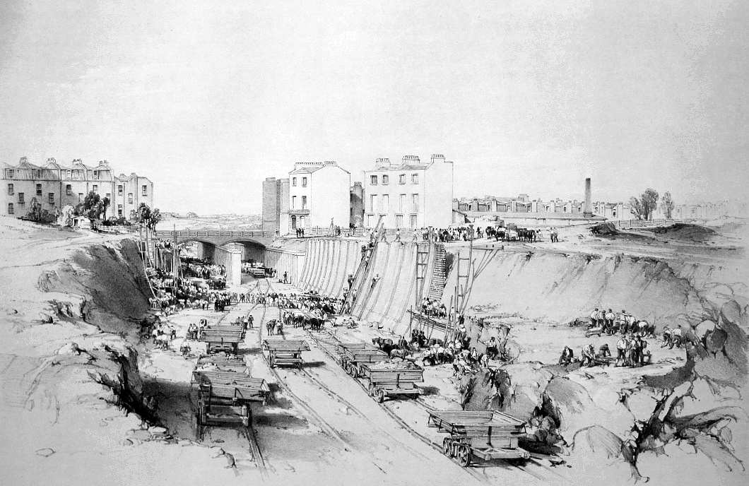
Forming the Boxmoor
Embankment bottom-up.
View of the Boxmoor embankment, when in progress,
shewing the method of forming it, from a side cutting, with horse-runs.
John Cooke Bourne, June, 1837.
|
The Boxmoor embankment (above) near Hemel Hempstead was formed in
this way, the spoil being lifted up the side of the embankment in a
hazardous procedure involving ‘horse-runs’:
“Over Boxmoor the railway is continued on an embankment, formed
with materials conveyed from adjacent cuttings. The
ballasting, &c., was raised from the surface on each side of the
line by horse-runs, as shown in the drawing, No. XVII.
[above] The horse, in moving along
the top of the embankment, draws the rope attached to a wheelbarrow
round two pulleys, and thereby raises the barrow of earth up the
sloping board, together with the labourer who holds and guides it.
This is a dangerous occupation, for the man rather hangs to, than
supports the barrow, which is rendered unmanageable by the least
irregularity in the horse’s motion. If he finds himself unable
to govern it, he endeavours, by a sudden jerk, to raise himself
erect; then, throwing the barrow over one side of the board, or
‘run’, he swings himself round and runs down the other. Should
both fall on the same side, his best speed is necessary to escape
the barrow, which, with its contents, comes bounding down after
him.”
Introduction to
Drawings of the London & Birmingham Railway, John Britton
(1839).
The top-down method of forming an embankment was generally preferred
because it was quicker. It involved extending the formation
gradually, at its full height, from both ends. The spoil from
a nearby excavation was conveyed to the workings along a light
railway in what today might be referred to as tipper trucks, but
were then called ’earth wagons’. Each wagon was then run up
against a buffer placed at the end of the workings, the momentum
causing the wagon’s tray, which was pivoted, to swivel upright,
tipping its contents over the edge.

Earth wagon.
However, before the formation of an embankment could commence, the
earth wagons had first to be assembled, a task that Francis Conder
described in his memoirs:
“In a country town [Watford]
where almost everyone knows as much, or more, about his neighbours
business as about his own, the arrival and establishment of two
civil engineers was accepted as an outward and visible sign that,
for good or for evil ,the great railway experiment was about
actually to be made. Before long, one or two keen-visaged,
weather beaten Yorkshire and Northumberland men, neither graziers
nor farmers, nor mechanics, but seeming to possess some resemblance
to each of these active classes, found means of establishing
themselves in roomy farm-houses, where the rick-yard soon began to
assume the appearance of a carpenter’s yard. Then men set to
work in a field very near the mail coach road, where the hill
dropped rapidly to the valley, in constructing waggons of a form
utterly inconceivable either to a farmer or to a carrier. Cast
iron wheels, formed with the flange which is now so familiar to
every loiterer at a railway station, but which was then an
unexplained puzzle to most folk, were firmly keyed on to solid
axles; a ponderous oak framework was fixed on the axles, and a
special provision was introduced, for tilting up the large shallow
tray which rested on that framework. A stout, hale,
well-humoured Yorshireman stood or sat in this field from early
morning till sunset, and inspected the progress of the waggon with a
never-flagging interest. People came to stare at him as much
as at his labourers.”
Personal Recollections of English Engineers,
F. R. Conder (1868).
The Yorkshireman with the never-flagging interest was possibly James
Copeland, contractor for the Watford to Kings Langley section, which
included the long Watford tunnel (and its deep cuttings at both
approaches) and the Hunton Bridge embankment. However, writing
in the Biographical Dictionary of Civil Engineers,
Mike Chrimes suggests John Willans Nowell, contractor for the Harrow
section.
When the earth wagons had been assembled, work on the embankment
could begin. By this date horses were being replaced by
contractors’ locomotives, especially where there was a considerable
distance ― ‘the lead’ ― between the excavations where the spoil was
to be obtained, and the embankment where it was to be deposited.
At some point along the embankment workings, the track on which the
earth wagons ran would be fanned out through a system of points, to
four or even six lines, to enable tipping to take place across the
full width of the embankment.
Robert Rawlinson, assistant engineer for the Blisworth section
(and later a sub-contractor), described tipping spoil over the end
of a forming embankment, a dangerous practice known as ‘teeming’:
|
 |
|
The
tip. |
“The ‘tip’ is the place
where the material is teemed over to form the embankment; the tip is
a removable point in a long embankment; the extreme end of the
embankment; and in a heavy embankment, such as the Blisworth, at
least 40 or 50 feet in height, it was a most difficult operation,
with the material they had to work, to keep these tips at their
ordinary level. To do so they were constantly obliged to raise
the levels, and run up hill a portion of the line; but supposing
they had got the ‘tip’ 10 feet high in the morning, perhaps tomorrow
morning they would find it 15 feet below the proper level . . . .
Subsided or slurred out at the sides. To do this work, the
rails are laid in long shunts; there are five or six lines of
railway at the tip-head, branching out of the two lines leading to
it. To run the waggons onto these shunts (sometimes the engine
would be on a road that was partially formed), the train of waggons
attached by a long chain 30 yards behind the engine; a velocity was
given to the engine and communicated to the waggons, and the engine
was then suddenly stopped, and a pair of points turned behind it,
and the waggons were then run in forward, that they might be tipped
into the embankment. Horses were employed to run the separate
waggons down to the tip-head, and when the end of the embankment was
raised above its level, they would take a short run for the horse to
get the waggon into motion and give it momentum, so as to carry it
on to the tip-head; and sometimes waggon, horse, men and all would
go over . . . .”
Robert Rawlinson
― Select Committee on Railway Labour (1846). |
――――♦――――
EXCAVATING CUTTINGS

Contractor’s locomotive
hauling a train of earth wagons in a cutting near Berkhamsted.
View of a cutting and bridge near Berkhamstead
(sic.), looking N.W.: shewing part of the town.
John Cooke Bourne, June 1837.
|
Building the London and Birmingham Railway involved upwards of 12
million cubic yards of excavation, or over 100,000 cubic yards of
earthwork per mile. The heaviest cutting on the line is at
Tring ― 2½ miles long, averaging 40 feet deep, the greatest depth
being 60 ― from which something over 1,400,000 cubic yards (approx
1.1 cubic metres) of spoil were removed.
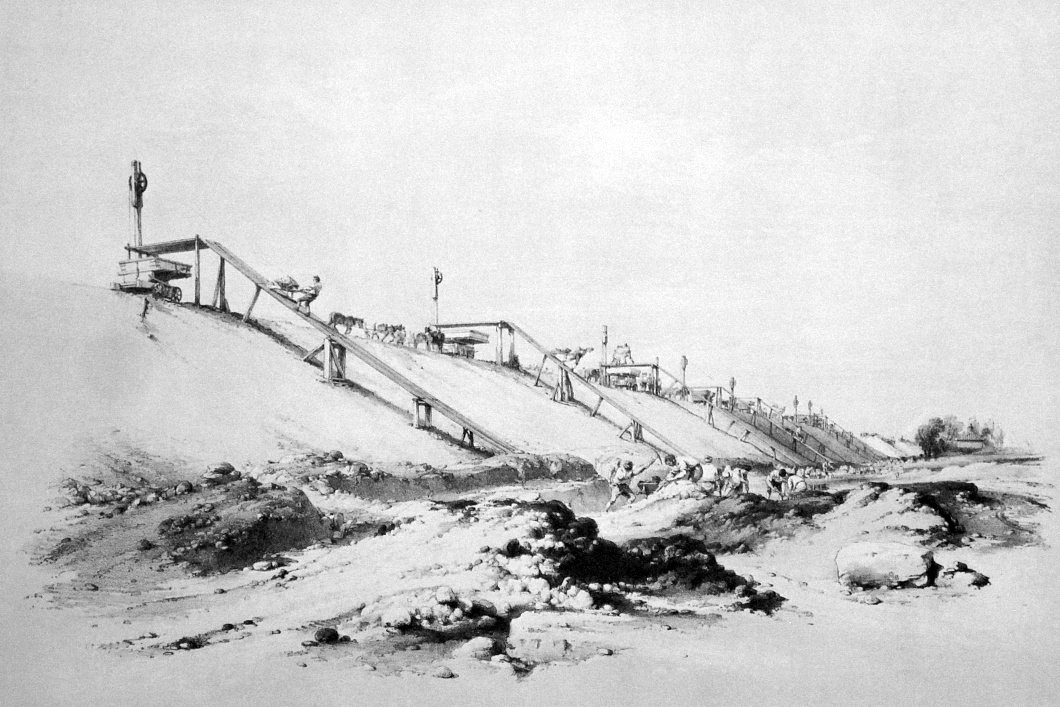
In some respects the approaches to excavating a cutting were similar
to those for forming an embankment. One was to barrow the
spoil out of the workings with the use of horse-runs (described
above), as is depicted in J. C. Bourne’s famous drawing of the Tring
Cutting excavation (below). The advantage of using horse-runs
was that many teams of labourers could be put to work simultaneously
along the full length of the cutting, rather than being restricted
to working inwards from the two extremities:
“Although there were thirty to forty horse-runs in the Tring
cutting constantly working, during many months, and each labourer
was precipitated down the slope several times; such, from continual
practice, was their sure-footedness, that only one fatal accident
occurred. A moving platform was invented by the engineer to
supersede the necessity of thus risking life and limb, but the
workmen, who considered it was designed to lessen their labour and
wages, broke it.”
Introduction to
Drawings of the London & Birmingham Railway, John Britton
(1839).
This method was most useful in circumstances where the spoil was not
to be carried away, but consigned to adjacent spoil pits, although
at Tring, part of the spoil excavated probably went into forming the
6-mile long embankment to the north of the cutting. |

Excavating the Tring
Cutting.
View of the deep cutting near Tring, with horse-runs, &c.
John Cooks Bourne, June 1837.
|
The alternative approach was to excavate from a cutting’s
extremities and convey the spoil away in trains of earth wagons.
This involved first creating a working faces at each end of the
section of rising ground through which the cutting was to be driven.
A trench or ‘gullet’ was then cut into the face of sufficient
breadth to accommodate a railway and train of earth wagons.
Excavation then took place at each side of the gullet, the spoil
being tipped into the waiting earth wagons below:
“In starting an excavation through a hill of considerable height,
it is desirable to get a fair face to the work, that is, one at
right angles with the direction of the cutting; and from this face
to start a system of gulleting or notching, by which labour is much
economised . . . . As the work proceeds into the hill, and the width
is increased to provide for the slopes, it becomes desirable to run
a ‘gullet’ along the centre of the cutting, in order to bring the
greatest number of [earth]
waggons into use. Thus the temporary rails being laid in the
gullet, a train of waggons is sent forward these receive all the
produce of the harrowing on either side, which is advantageously
prosecuted in advance and alongside of the waggon-filling, for the
purpose of keeping the work level for starting the next stage or
layer of excavation.”
The Practical Railway Engineer,
G. D. Dempsey (1855). |
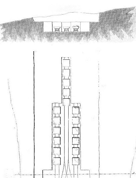
|

Above: excavating a cutting. A face is
formed, then one or more gullets are driven into it of sufficient
width to accommodate a train of earth wagons. The gullets are
driven forward as the work proceeds.
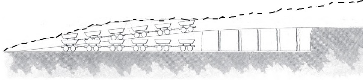
Below: this scheme in section and in plan as the
gullets are driven forward, showing the trains of earth wagons.
Spoil was shovelled or barrowed down into the wagons from both sides
of the cutting, which is gradually widened out:
“By the aid of the gullet the wagons can be brought close
alongside the material to be moved, and a couple of men being set at
work on each, the soil is deposited in them with an ease and
celerity far surpassing that which would be required had each
spadeful to be conveyed even for the distance of a few yards.
Meanwhile, as the stuff is removed by the workmen on either hand,
the gullet is continued into the hill by those a-head, while lumps
are showered into the wagons on all sides.”
Our Iron Roads,
Frederick Smeeton Williams (1852). |
|
 |
|
 |
|
Excavating at two levels: excavation was performed in
layers. As one layer was completed, another was started at a
lower level until the required depth was reached. |
Excavating a railway cutting.
Excavation at Park Village, showing the works in
progress. John Cooke Bourne, September 1836.
――――♦――――
|
INSTABILITY IN CUTTINGS AND
EMBANKMENTS
In the sense in which it is used here, instability refers to the
failure of earthworks resulting in slip:
“SLIP, or LAND-SLIP
― a slipping of the earth of a cutting, or embankment, which most
frequently occurs in the case of deep cuttings and high embankments;
they generally arise from the want of stability of the soil, and
general badness of foundation, also from the side-slopes being
formed too steep; but clayey soil will slip at almost any slope,
good drainage is, therefore, important in earthwork.”
A
Glossary of Civil Engineering, S. C. Brees
(1841)
Slip was a problem that occurred at a number of points along the
Railway, sometimes several years after the earthwork in question had
been completed, this being referred to as ‘delayed slip’.
One cause of slip resulted from building the slopes of embankments
and cuttings at a steeper angle than that at which the material in
question would lie naturally at rest without slipping, its ‘angle of
repose’. But the steepness of a slope is not a straightforward
question to decide, for the angle of repose not only varies for
different materials, but can also be affected by the amount of
moisture they contain. For instance, a wall of damp sand can
be built almost vertical (as those who have seen the work of seaside
sand artists will appreciate); a pile of sand, when wet, will lie at
45º to the horizontal; when dry, at 34º; but when saturated, the
angle of repose reduces to as little as 15º. Sir Henry
Parnell’s much respected treatise on roads (based on the work of
Thomas Telford) offered this advice on the slope of cuttings and
embankments, and on the need for consolidation:
“When it is necessary to make a deep cutting through a hill, the
slopes of the banks should never be less, except in passing through
stone, than two feet horizontal to one foot perpendicular; for
though several kinds of earth will stand at steeper inclinations, a
slope of two to one is necessary for admitting the sun and wind to
reach the road. The whole of the green sod and fertile soil on
the surface of the land cut through should be carefully collected
and reserved, in order to be laid on the slopes immediately after
they are formed. If a sufficient quantity of sods cannot be
procured in the space required for the road, the slopes should be
covered with three or four inches of the surface mould, and hay
seeds should be sown on it; by this plan the slopes will soon be
covered with grass, which will be a great means of preventing them
from slipping.”
A Treatise on Roads, Sir
Henry Parnell (1833).
Before the first London and Birmingham Railway Bill was placed
before Parliament in 1832, the Company commissioned two experienced
civil engineers to review Stephenson’s plans for the line; they were
Henry Palmer (1795-1844) and John Urpeth Rastick (1780-1856).
At the committee stage in the House of Lords, both engineers gave
evidence, in the course of which they expressed their opinions on
the angles that Stephenson planned for his slopes. Of the two,
Rastick’s views are the more enlightening; while generally content
with Stephenson’s plans, as was Palmer, he felt that shallower
slopes were advisable, especially were banks were to be formed in
London clay. But shallower slopes meant wider structures,
which in turn meant that more land had to be bought and more
material had to be excavated:
“Regarding the slopes, generally speaking, I agree with Mr.
Stephenson; perhaps there are instances in which it may be prudent
to increase them. I made a calculation of them at 3 to 1,
instead of what they are stated at by Mr. Stephenson, which made an
addition of £17,303; but I should not be inclined to make them as
much as 3 to 1, (I have not had experience in London clay).
Where the cuttings are shallow 2 to 1, or less, is quite sufficient,
and there are few cuttings of great importance along the line.
Mr. Stephenson makes his deep cuttings 2 to 1, and his shallow
cuttings 1½ to 1. One of the principal cuttings is at Primrose
Hill, there is another, rather deep, where he crosses the London
Road to Harrow, perhaps it may be necessary to increase these slopes
to 2½ to 1, the expense of which would be under £5,000. In
works of this nature slips will occur, even in the best material.”
John Rastrick,
from Railway Practice, S. C. Brees (1839).
Speaking some years later about the construction of the Colne Valley
embankment, the Resident Engineer, G. W. Buck, informed a
parliamentary committee [5] that this embankment
had been made shallower than the angle of repose for the spoil from
which it was formed:
“The Watford Embankment is at present about 32 feet high; the
Permanent Angle of the Slopes is 2 to 1; but the Natural Angle at
which the Soil will stand immediately after teaming (the Angle of
Repose) is about 1½ to 1, which enables us to make the Embankment
temporarily wider at the head (as it is called by the workmen) and
get in 6 Teaming Lines of Road: after the Line has passed that
particular point, the work is trimmed down to 2 to 1, as it is no
longer required.”
G. W. Buck, from
Railway Practice, S. C. Brees (1839).
On the face of it, using the spoil from a cutting to form an
embankment seems the sensible thing to do, but the material can
sometimes be unsuitable for the purpose. The great Wolverton
Embankment is an example. It was formed on the cut and fill
principle using, in part, Oxford clay excavated from a nearby
cutting, with serious consequences:
“In the formation of the embankment at Wolverton, great
difficulties were encountered . . . . The length of the embankment
being one mile and twenty eight chains (deducting the viaduct), and
the height of a great part of it forty eight feet, some accidents
were to be expected, especially in bad weather; but no one could
have imagined what would take place on the south side of the
viaduct. Here the material, at the commencement, was composed
of sand, gravel, and blue clay: this stood very well; but when the
workmen went deeper into the cutting, they excavated some black,
soapy clay; this was tipped on to a turf bottom, and the weather
being also very unfavourable, although every care was taken to mix
dry stuff with the wet material, yet there occurred one of the
worst, if not the worst slip, along the whole line. Earth was
tipped in for day and days, and not the slightest progress was made;
as fast, in fact, as it was tipped in at the top it kept bulging out
at the bottom, till it had run out from 160 to 170 feet from the top
of the embankment; and at last a temporary wooden bridge was formed,
and, by wagoning the earth over this, the embankment between the
slip and the viaduct was formed, by first digging a trench, five
feet deep, and nearly the whole width of the embankment, and forming
a mound on each side to prevent it from giving way.”
The London and Birmingham Railway,
Roscoe and Lecount (1839).
|

Forming the Wolverton
Embankment.
View of the embankment near Wolverton, during its
progress: shewing the manner of forming embankments,
and an accidental slip of earth. John Cooke Bourne, June 1837.
|
Likewise, the banks of cuttings driven through some types of strata
also have a tendency to instability. Much difficulty was
experienced excavating the Blisworth cutting:
“In the case of the great Blisworth cutting
the strata were unequal in consistency. About halfway up the
face of the cutting a stratum of limestone rock, 25 feet in
thickness, was found, with loose strata below and above it, and it
was necessary to prevent the lower stratum, consisting of wet clay,
from being forced out under superincumbent mass by undersetting.
A rubble wall, averaging 20 feet in height, was built on each side
underneath the rock, strengthened by buttresses at intervals of 20
feet, resting on inverted arches carried across underneath the line.
A puddle-drain was formed behind each wall, with a small drain
through the wall to let off the water from behind.

Fig. 13 is an elevation of the west end of the
cutting where it is about 40 feet deep, showing clearly the method
of undersetting, and fig. 14 is a cross section of the side walls at
the same place, where the left-hand shows a section of the wall in
the water, and the right-hand side shows the section through a
buttress, together with the invert and drains. One of the
walls is shown in front elevation in fig. 15.”
Encyclopedia Britannica
9th Edition (1902).
During the construction of the line, formations in clay gained a
notorious reputation, particularly when the material was poorly
compacted. In some clays, the particles from which they are
formed are loosely packed, allowing water to enter the body of the
structure, which then softens and weakens it. Furthermore,
when clay dries out, fissures form within it that also allow the
ingress of water, a problem that civil engineers of an earlier
generation discovered when dealing with leakage in canals. A
further complication ― if one were needed ― is that this softening
process in clay embankments and cuttings does not necessarily happen
quickly; the ingress of water into a structure is sometimes slow,
but progressive, taking several years before it is sufficiently
weakened for failure to occur. Such a delayed slip occurred in
the Bugbrooke cutting (Upper Lias clay) in 1842, several years after
its completion:
“ACCIDENT ON THE LONDON AND
BIRMINGHAM RAILWAY.
― The following official report has been addressed to the Board of
Trade, on the subject of a slip at the Bugbrooke excavation on
Saturday last, by Mr. Creed, the indefatigable Secretary to the
Railway: ―
‘Sir, ― I am instructed to report to you for
the information of the Lords of the Committee of Privy Council for
Trade, that in consequence of a slip, about 50 yards in length,
which occurred on the down side of the Bugbrooke excavation of this
railway half-way between the Blisworth and Weedon stations, about
four o-clock in the afternoon of Saturday the 24th inst., several
thousand cubic yards of earth covered both lines of rails, and
obstructed for a time the regular passage of the trains.
By extraordinary exertions, however, the up line was cleared before
eight o’clock the same evening; and the up as well as down trains
have since continued to pass uninterruptedly over it. Both
lines will, it is expected, be clear in the course of this week.
The only practical inconvenience which resulted from this occurrence
(for it was happily unmarked by casualty), was the exchange of
passengers between the carriages of the York up train and the 1h
30min. p.m. down train on the opposite ends of the slip, and the
delay of rather less than two hours in the arrival of the two other
trains.
The surface of the ground, both above and on the face of the
excavation, had presented no previous appearance to indicate a slip;
but the attention of the overlooker of the road and engine-man of
the 9h. 45min. a.m. down train having been called to this point by a
slight deflection of the rails of the down line inwards, it was
carefully watched. The company’s engineer is desired to
examine the slip, and to report as to the immediate cause.
I have the pleasure to add, that the directors have every reason to
be satisfied with the strict observance of regulations, and the
zealous exertions which were manifested on this occasions by every
person in their employ.
I have the honour to be, Sir,
Your most obedient servant,
R. Creed, Secretary.’”
The Northampton Mercury,
1st October, 1842.
Extra precautions ― in the form of shallow slopes, counterforts [6]
and retaining walls ― had therefore to be taken when excavating and
repairing cuttings in clay soils, and good drainage was essential.
Another cause of instability lies in the nature of the ground, which
might be too soft to support an embankment’s weight. Following
its completion, the long embankment across the Colne Valley suffered
slippage due to its foundation sinking:
“The whole of the land near this spot is most precarious in
stability; and the effects are clearly visible in the amazing
‘slips’ which have taken place in the embankment across the valley.
Oftentimes, in a very few hours, the level of the newly-formed
ground has sunk several feet, while the base of the embankment has
widened out to an enormous extent, causing infinite labour to bring
the level of the Railway back again to its original state, and to
make it solid enough for the passage of the trains; this has caused
many a sleepless night to the workmen and engineers. The
length of this embankment is about a mile and a half, and is
composed entirely of the finest materials for such a purpose ― chalk
and gravel.”
The London and Birmingham Railway,
Roscoe and Lecount (1839). |
――――♦――――
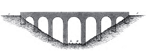
VIADUCTS

Wolverton Viaduct crossing
the valley of the Great Ouse.
|
The following extract is from Stephenson’s specification for the
Lawley Street viaduct. Its construction formed contract 1G,
dated August 1834, the contractor being James Nowell & Sons . . . .
“This Bridge or Viaduct, is for the purpose of carrying the
Railway on a perfectly level plane over Lawley Street, and the two
branches of the River Rea. It will consist of ten arches, each
50 feet span; the soffits of all the arches being brought to the
same horizontal line, at the height of 23 feet 6 inches, above the
level of the present surface of Lawley Street at its intersection
with the centre line of the Railway.
The Arch passing over Lawley Street will be built askew to suit the
angle of intersection of the street with the Railway, the remaining
nine to be built square.
The Direction of the bridge must be curved at a radius of one mile
and a quarter, so that the parapet walls shall be parallel with the
lines of Railway.
The Bridge must be built of brick with stone arch quoins
springing-course, string-course, plinth, and coping. Each
front will have two projecting pilasters, and the ends of the piers
will project from the face line of the arch in the manner shewn in
the Drawings No 1 and II.
All the Arches will be segments of circles and of similar form on
each front of the bridge . . . .”
From this it can be seen that a viaduct is a type of bridge composed
of multiple spans. In the case of the Lawley Street Viaduct it
was ten, the central span being skewed (skewed bridges are described
below).
In the context of a railway, viaducts were built to convey a line
over an obstruction,
on the level (viz. para. 1 of the extract above). This
might be a depression in the surrounding land, such as a river
valley; buildings in a built-up area of a town; or a major road,
especially where there was a considerable height difference between
road and rail. Some very considerable viaducts were built on
British railways, that at Ribblehead on the Settle and Carlisle line
being well known to railway enthusiasts . . . .

The former
Midland Railway viaduct spanning the valley of the River Ribble,
North Yorkshire. Photo:
chantrybee.
Viaducts often fulfil the same purpose as embankments, which had the
general advantage in construction cost from being able to utilise
the spoil from nearby excavations. However . . . .
“. . . . as elevations are increased, embankments lose their
superiority over, and are soon superseded by, viaducts. This
is chiefly owing to the rapidity with which their sectional area is
increased as they become elevated, and the consequent large quantity
of land they require. These increasing effects are not
experienced in a viaduct.”
A Practical Treatise on the Construction and
Formation of Railways, James Day (1848).
But as the century progressed, the economic balance between
embankment and viaduct appears to have altered, to the extent that
viaducts became generally the cheaper option:
“During the development of the railway system in Britain, the
economy of bridge building has necessarily received much attention,
and has been illustrated by a multitude of structures, exhibiting
many varieties of design and of material. That this vast
experience has led to substantial improvements, and to saving in
cost, may be inferred from the fact, that in many cases bridges and
viaducts of great extent are now adopted in preference to mere
earthworks, ― a long viaduct being now available at less cost,
original and current, than an embankment of similar extent; whereas,
in the early experience of railway making, it is well remembered
that the most expensive earth-work was almost invariably adopted,
both for economy and ultimate sufficiency, in preference to any
description, then approved, of bridge work.”
The Practical Railway Engineer,
G. D. Dempsey (1855).
Viaducts were not necessary for bridging streams and minor roads,
which were crossed using a short bridge built into an embankment, or
taken under an embankment through a culvert or tunnel.
However, where a crossing of significant breadth was encountered,
such as the Colne Valley (Watford) and the valley of the Great Ouse
(Wolverton), the practice on the London and Birmingham Railway was
to combine a viaduct with an embankment:
“Immediately after resuming our journey, we cross the Grand
Junction Canal by a handsome stone and iron bridge, and enter upon
the colossal embankment, which carries the [rail]
road across the Vale of Wolverton. At a short distance from
the canal we cross the rivers Ouse and Tow, by a handsome brick
viaduct, whose magnificent stupendousness will be better understood
by reciting its various proportions.

It consists of six elliptical arches, each sixty feet span,
springing, at a height of twenty one-feet from the ground, from
piers ten feet in thickness; the height, from the crown of the
arches to the basement of the piers, is about sixty feet. The
whole length of this viaduct, including the brick facing on each
side of the arches, is about one-eighth of a mile. In forming
this viaduct, it was found necessary to divert the original courses
of the Ouse and Tow. They now flow on together beneath this
viaduct, in one spacious channel paved with brick.”
The London and Birmingham Railway Guide,
J. W. Wyld (1838).
Civil engineering advice of the times warned of the importance of
erecting piers on firm foundations, especially in the case of a high
viaduct, where a considerable weight bore down on a comparatively
small area of foundation:
“For structures of this magnitude, the sufficiency of foundation
is of the first importance: the greater altitude not only imposes
greater weight of materials to be supported, but also evidently
requires that the cohesion of the foundations, and indeed of the
whole structure, be more perfect, as any defect or dislocation is
more likely to occasion extensive mischief in proportion as the
height is increased. If gravel or chalk can be reached, with a
good bed of concrete nothing need be apprehended; but if loam, sand,
or bog occurs, piling is found the better expedient.”
The Practical Railway Engineer,
G. D. Dempsey (1855).
Occasionally, excavating the foundations for viaduct piers unearthed
the unexpected:
“Now for another curious ‘find’. On the line of the London
& Birmingham Railway I had to build a viaduct over the River Avon
between Wolston & Brandon Villages. On examination as to the
foundations to be expected I discovered that below the bed of the
river there were 25 feet in depth of peat lying on a bed of firm
gravel. This I found out by pushing down a long bar of iron.
To reach the gravel it therefore became necessary at each of the
abutments and piers of the viaduct to construct what are called
coffer dams, formed of planks driven down through the peat and into
the gravel to enable us to build up the foundations.
When the coffer dam was complete, we course had to excavate the
black peat. On arriving within about 5 feet of the gravel we
found complete trees lying, of course, on their sides with all their
branches crushed down quite flat: you may imagine our surprise to
find quantities of hazel nuts in the peat amongst the branches.
Of course they were very black and soft. I took out a large
quantity of them hoping to dry and keep them as a curiosity ― but as
they became dry they crumbled to dust. We went on sinking in
the same character of black stuff formed of coarse peat till the
gravel bottom was reached, but here our surprise was doubled for,
lying on the surface of the gravel we found skulls of the short
horned breed of oxen, quite complete with teeth, horns and all, with
a great number of bones not only of oxen but of sheep, hares &
foxes, and most wonderful of all, the leg bone of an elephant!”
The Dairy of John Brunton
(ca. 1890).
The viaduct to which Brunton refers is the London and Birmingham
viaduct, one of two railway viaducts that cross the River Avon near
Rugby. The other, Rugby Viaduct, is a now abandoned structure
on the former Midland Counties Railway between Rugby and Leicester.
[7] |
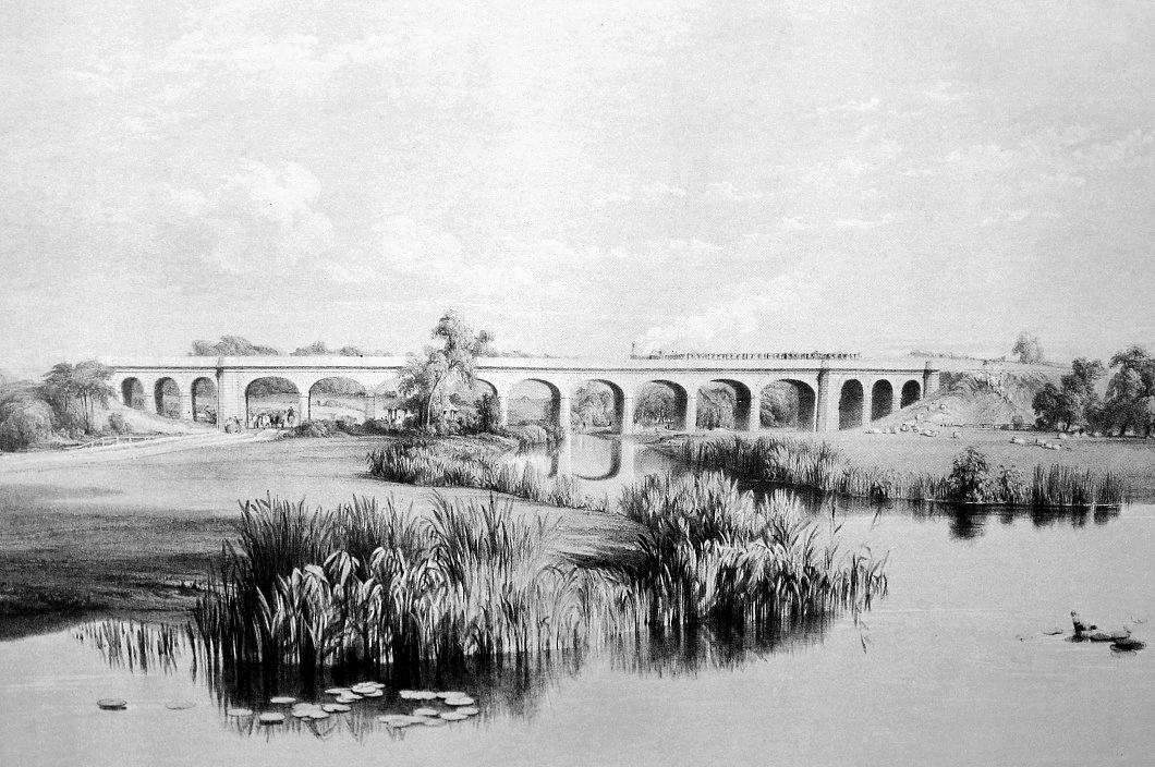
West side of the viaduct
over the River Avon, near Wolston. John Cooke Bourne.
|
The London and Birmingham Railway viaduct is now Grade II listed,
the English Heritage description of it reading:
“Railway viaduct. c.1835. Brick faced
with rusticated sandstone ashlar with strongly projecting moulded
string course, and coped parapet. 9 elliptical arches and 6
narrower subsidiary round arches have rusticated voussoirs.
Canted piers between each arch. Larger piers between main and
subsidiary arches and to ends have octagonal caps. 2
subsidiary arches to west are bricked up and largely hidden by the
embankment. Built for the London and Birmingham Railway.” |
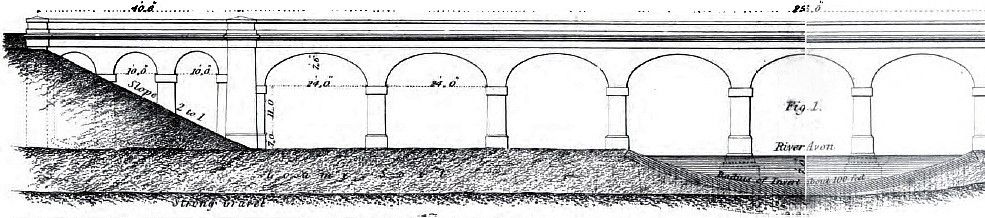
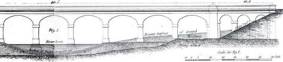
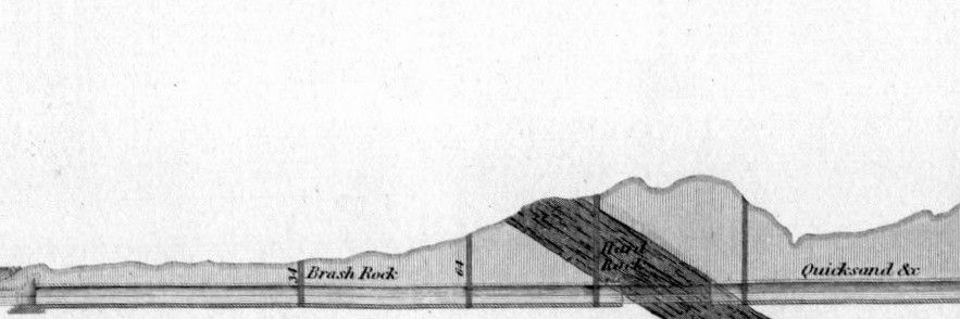
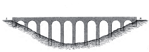
Elevation of the River Avon
Viaduct, London & Birmingham Railway.
|
“This viaduct, of which the total length is about 350 feet,
consists of nine semi-elliptical arches, 24 feet span, and 7ft. 6in.
rise, and three semicircular arches at each end, of 10 feet span,
faced entirely with stone. Each of the six end arches has a
brick inverted arch between the piers above the foundations, which
are carried along uniformly in a solid bed beneath these arches,
with such steps and at such levels as the nature of the substratum
required. The three middle arches have an inverted arch of
brick-work
[visible in the drawing], which forms an
artificial channel for the river. This invert is faced at each
end with a row of sheet piling, driven through the loam into a bed
of strong gravel beneath. All the foundations which do not reach
this gravel are built upon thick beds of concrete, and a layer of
the same material covers the whole of the arches, forming a level
bed for the gravel in which the sleepers of the railway are laid.”
The Practical Railway Engineer,
G. D. Dempsey (1855).
――――♦――――
TUNNELS

A levelling party
at work, Primrose Hill Tunnel.
“TUNNEL:
a subterraneous gallery or passage excavated or dug through the
earth for the passage of a canal, road, or railway.”
A Glossary of Civil Engineering,
S. C. Brees (1844).
“TUNNELS: The principal tunnels on this [London and Birmingham]
line are those of Primrose Hill, which is 1120 yards in length;
Kensal Green (curved), 320 yards; Watford, 1830 yards; Leighton
(curved) 272 yards; Weedon, 418 yards; Kilsby, 2398 yards; and
Berkswell, 300. The Kilsby tunnel, which is by far the chief
work of the kind on this railway . . . .”
The Railways of Great Britain and Ireland, Francis Wishaw (1842).
Tunnelling is a further means of reducing gradient, although whether
that approach was to be preferred to excavating a cutting depended
on circumstances:
“The choice between
the two methods will depend on the nature of the soil at the
dividing ridge, and the comparative expense of the two methods: in
general, it is said, that tunnelling is to be preferred to deep
cutting when the depth to be excavated is above sixty feet; and,
also, when the cost of a running yard of each is the same, it is
said that deep cutting is generally to be preferred, from the
greater facility and despatch with which it can be done.”
An Elementary Course of Civil Engineering,
Dennis Hart Mahan (1838).
Other factors for the civil engineer to consider were whether a
short tunnel with long approach cuttings was preferable to a longer
tunnel with shorter approaches; similarly, whether a short tunnel
under a high point of the ridge was preferable to a longer tunnel
under a lower point. In each case the cost of sinking shafts
needed to be considered, while the nature of the ground and its
tendency to slip was a factor to consider in deciding the length of
the approach cuttings; and while cuttings posed the risk of slip,
tunnelers had to face that of the roof collapsing before ― and
possibly after ― a lining had been put in place:
“In soils which required to be arched, it is seldom
safe to sink the working shafts directly over the crown, as they
would weaken the earth and might occasion cavings-in. It is
therefore recommended, in such cases, to mark out the lines of the
piers of the arch, and to sink the working shafts ten or fifteen
feet on the outside of these lines. ”
An Elementary Course of Civil Engineering,
Dennis Hart Mahan (1838).
This advice appears not to have been taken by the contractor
excavating the Watford Tunnel, when one of the working shaft
collapsed above the tunnel arch:
“In tunnels bored through chalk, it is often necessary
to act with great caution, as it sometimes contains large holes
filled with gravel, which, on being opened during the execution of
the works, pours in on the unsuspecting miner like water. Thus
in the Watford tunnel, which passes through the upper chalk
formation, where it is covered with a thick irregular bed of gravel,
such breakings-in occasioned great inconvenience and delay.
The chalk fissures, sometimes a hundred feet in depth, filled with
gravel, which when worked into, ‘rushed down with such violence, as
to plough the sides of the tunnel as if bullets had been shot
against it.’ Such an accident, occurring at the foot of one of
the working shafts, overwhelmed ten men who were there at work . . .
.”
Our Iron Roads, F. S. Williams (1852).
The approach to tunnelling was developed by the canal engineers.
This was further refined at Blisworth, on the Grand Junction Canal,
where James Barnes drove a small pilot heading (or ‘driftway’) in
advance of the main excavation, mainly to assist drainage, but it
also provided a more complete examination of the strata while
providing a further check on the tunnel’s correct alignment.
The alignment of the tunnel having been decided, the first task was
to mark this out with pegs on the ground above. In setting the
direction, when one end of the tunnel was not visible from the
other, ranging towers were built to assist with alignment, although
by the time the London and Birmingham Railway was built reliable
Ordnance Survey maps were available. It was then necessary to
test for the presence of any potential hazards in the underlying
strata ― subterranean watercourses, quicksand, gravel and unstable
formations ― that might make necessary a change in the tunnel’s
alignment, by making trial borings to collect samples:
“A careful
preliminary examination is made of the geological strata, so far as
these can he discerned from the external features of the country;
and levels or soundings are taken, from which a profile of the
surface of the ground to be passed under may be formed. To
test the character of the underground strata, before letting the
works to contractors, vertical borings are made through the site of
the proposed tunnel, or trial shafts are sunk with the same object.
No matter how thorough this preliminary examination may be, the
nature of the strata throughout cannot be ascertained with perfect
accuracy; and it may so happen, as in the case of the Kilsby Tunnel,
that the most dangerous part of the ground may not be disclosed.”
‘Difficulties of Railway Engineering’,
The London Quarterly Review,
Issue 205 (1858). |
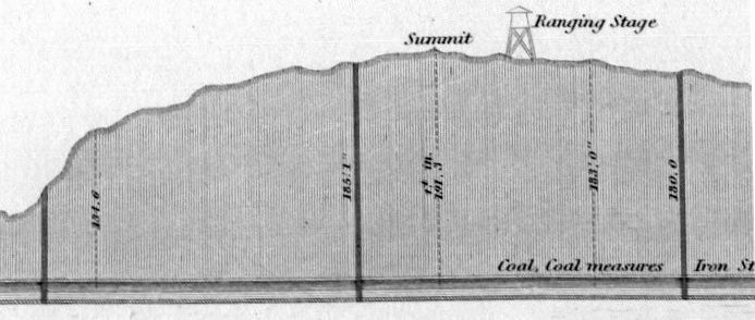


Section through
Telford’s Harecastle Tunnel showing a ranging tower and exploratory
shafts.
|
Excavation was commenced from each end of the tunnel, and from the
bottom of working shafts sunk at intervals along the tunnel’s
length. A small heading was first driven between the shafts,
and carried on through the length of the tunnel; this served to
verify its alignment and level. Francis Conder, a pupil of
Charles Fox, left an account of the completion of this stage of
excavating the Watford Tunnel:
“The line through the tunnel was
straight, and had been set out and pegged over the surface, as in
other portions of the route. At every furlong in length a
shaft had been sunk, with the intention of opening a drift way (a
small heading) from end to end, and thus running both line and level
through under ground, before commencing the main excavation and
lining of the tunnel, which it was intended to carry on through
three of these shafts, properly enlarged, using the others for
ventilation . . . . a week after the completion of the headway, ―
which week had been spent in knocking off elbows here, raising the
roof there, and lowering the floor in another place, with occasional
loss of time and of temper, as some intruder came blundering through
the long narrow cavern, ― the pupil of the sub engineer,
[Conder]
the only one of the staff left on his legs, had the extreme
satisfaction of viewing the red signal lamp, fixed at the north end
of the head-way, from the southern extremity, over a regular and
exact line of candles, one close to each shaft. The question
of the direction of the tunnel was thus solved . . .”
Personal Recollections of English Engineers,
F. R. Conder (1868).
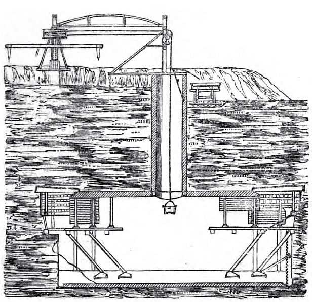
Above: longitudinal section
through a tunnel under construction,
showing a shaft, worked by a
horse gin, and two working faces.
Below: a horse gin.

――――♦――――
BRIDGES
A bridge provides a means of crossing a waterway or highway.
In common with a viaduct, a bridge is not a structure for regulating
a railway’s gradient. However, this chapter is the most
appropriate place in which to describe some of the bridges on the
line that were constructed under Stephenson’s direction.
Generally speaking, the situations in which the need for a bridge
arises are where a railway and highway or waterway intersect either
on the level, or at different levels. Each requires a
different bridging solution, depending on whether the intersection
is at a right angle, or an oblique angle ― the latter introduces
complications when the bridge is to be built from bricks and/or
masonry.
Where a railway and highway intersected on the level, the cheapest
solution was to build a level-crossing. While this required
minimal civil engineering, it introduced safety implications,
especially on a mainline carrying high-speed traffic. [8]
The alternative was to raise or lower the road to provide sufficient
clearance, it being impractical to alter the level of the railway. [9]
In considering where the balance of advantage lay in the two
approaches, the following advice was offered:
“In economy of brickwork, the bridge in cutting has the
advantage, as the footings require to be sunk only 18 inches or 2
feet below the slope; while the bridge in bank . . . . will require
the abutments so much below the original surface. The latter
will also require fences on the approaches, which the former will
not. On the other hand, the bridge in cutting will involve
more expense in
drainage than the bridge in bank; and this consideration must
be entertained with full regard to the comparative levels of the
surrounding districts, and will frequently be found to outweigh all
the other advantages of the sunk bridge.”
The Practical Railway Engineer,
G. D. Dempsey (1855). |
|
 |
 |
|
Raised bridge |
Sunk bridge |
|
Dempsey then goes on to advise on the
situation where a road crossing needs to be made with a railway on a
shallow (approximately 16 feet) embankment, or in a shallow cutting:
“In either instance, the best structure will be obtained by
adopting a bridge with parapets parallel throughout, or very
slightly diverging from each other at each end; by making it
sufficiently long to allow easy slopes for the banks, an ample width
of road, and for the abutments to cut well into the slopes on each
side; thus dispensing altogether with wing or retaining walls which
are always expensive and seldom secure.”
The Practical Railway Engineer,
G. D. Dempsey (1855). |
|
 |
 |
|
Railway in
cutting |
Railway on
embankment |

An elegant bridge
built into the Blisworth Embankment.
The road leading from Towcester to Northampton.
|
Where there is a considerable difference in height between road and
rail, a viaduct then becomes necessary:
“. . . . where the difference of levels is very considerable, and
an extended structure or viaduct is required, economy of
construction becomes additionally important. A reduced
width of viaduct, so as to provide for one line of rails only, has
been sometimes recommended; but this is a kind of economy which can
be justified only under peculiar circumstances, and which may be
productive not only of much inconvenience and hindrance, but of
greater ultimate expense than the double width would at first
involve.”
The Practical Railway Engineer,
G. D. Dempsey (1855).
And where viaducts are concerned, Dempsey joins other commentators
in stressing the importance of the “sufficiency of foundations”
if “extensive mischief” is to be avoided. |
 |
 |
|
Railway in
cutting |
Railway on
embankment |
|
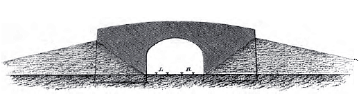
Where a highway and waterway intersect at
right angles, the abutments of a bridge built to negotiate the
crossing are parallel and stand opposite each other, and the courses
of brickwork or stonework are can be built up horizontally.
But a complication arises where the intersection is not a right
angle. Sir Charles Fox summed up the problem:
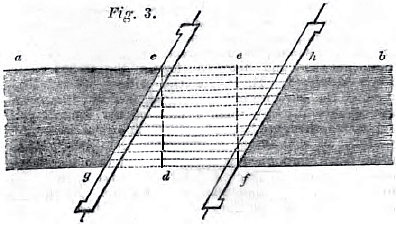
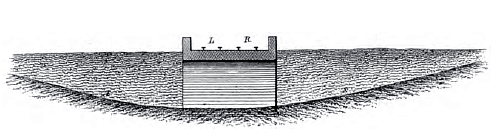
“Wherever a canal is thus crossed at an angle, we must either
divert the canal, so as to bring it at right angles to the railway
[Fig. 1 below]; or we must build a
common square bridge of sufficient span to allow the canal, its
course being unaltered, to pass uninterruptedly under it
[engraving below]; or we must erect a
proper skew bridge
[Fig. 2 below]. The first of
these is often impracticable, as provisions are generally inserted
in the Acts of Parliament, for preserving the canal from any
alteration in its course; and even if this were not the case, the
diversion of a canal causes great expense, and is attended with much
inconvenience to its traffic: the second is a most unscientific mode
of overcoming the difficulty, and would also involve very serious
expense arising from the necessity of making use of an arch of much
larger dimensions than would be required were the proper oblique
arch erected in its stead . . . . It is for the above reasons that
oblique arches are now so frequently erected; and a good method of
building them, is therefore, of considerable importance.”
On the Construction of Skew Arches,
Charles Fox (1836).


A common
square bridge of extra span, built at an angle ― odd-looking and
ugly.
A contemporary engraving showing the London & Birmingham Railway
crossing Watling Street,
near to the site of the temporary station at Denbigh Hall.
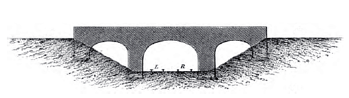
The ‘skew arch’ enables a bridge to span an obstacle at other than a
right angle, but when built of bricks and/or masonry ― the structure
then being built up in courses of brickwork and/or stonework ― the
construction is not straightforward. Although the bridge
abutments remain equal and parallel, they are no longer directly
opposite each other:
“In skew bridges, in order to keep the thrust in the proper
direction, it is necessary to place the courses of stones at an
angle with the abutment, whereby each stone loses its parallelism
with the surface of the road, and is therefore laid on an inclining
bed.”
On the Construction of Skew Arches,
Charles Fox (1836).
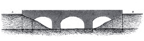
The eminent canal engineer James Brindley never succeeding in
working out a solution to the problem of constructing a strong
skew arch, and in consequence all his overbridges were built at
right angles to the waterway, with double bends in the roadway,
where necessary (as in fig. 1 above). To this day, many of
them cause inconvenience to their users:
“Down to that time [late 18th century] such bridges had
always been built in the same way as common square arches, the
voussoirs being laid in courses parallel with the abutments.
How very defective such an arch would he may be seen by reference to
Fig. 3, in which lines are drawn to indicate the direction of the
courses. It is evident that here the portion cdfe is
the only part of the arch supported by the abutments; the triangular
portions
cdg and efh being sustained merely by the mortar,
aided by being bonded with the rest of the masonry. This plan
could therefore only be adopted for bridges of very slight
obliquity, and even then with considerable risk.”
The Penny
Cyclopaedia, Vol. 22 (1842).
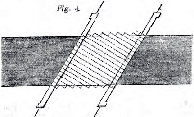
“About the time mentioned above, Mr.
Chapman [10]
was employed as engineer to the Kildare canal, a branch from the
Grand Canal of Ireland to the town of Naas, on which it was desired
to avoid diverting certain roads which had to be crossed. He
was therefore led to think for some method of constructing oblique
arches upon a sound principle, of which he considered that the
leading feature must be that the joints of the voussoirs, whether of
brick or stone, should he rectangular with the face of the arch,
instead of being parallel with the abutment. Thus the courses
instead of taking the direction shown in Fig. 3, were laid in the
manner indicated in Fig. 4
. . . . Mr. Chapman observes that the lines on which the beds of the
voussoirs lie are obviously spiral lines, and to this circumstance
may be attributed much of the singular appearance of oblique
arches.”
The Penny
Cyclopaedia, Vol. 22 (1842).
|
 |
|
 |
|
Masonry and brick
skew arch bridges. |
Various methods were later described for designing skew arches,
three that were put forward being developed by engineers who worked
on the London and Birmingham Railway ― Charles Fox, John Hart and
George Watson Buck. Each wrote a treatise on the subject, [11]
that by Buck becoming a standard text for many years. The
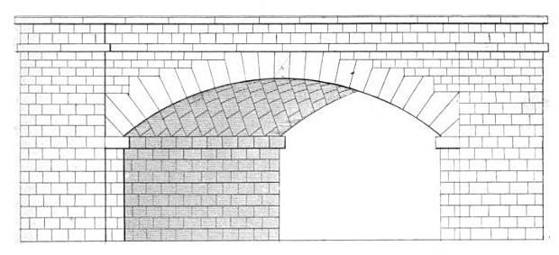
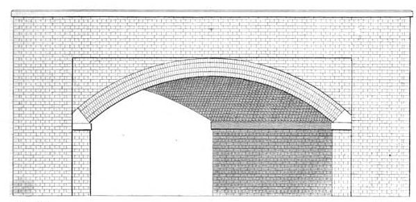
bridge carrying the London and Birmingham Railway over the London
Road at Boxmoor in Hertfordshire, adjacent to what is now Hemel
Hempstead station on the West Coast Main Line, is an example of a
‘segmental’ arch. It is constructed in masonry, with a brick
barrel, stone quoins and a 58° angle of skew. Designed by
Buck, it was completed in 1837.

Boxmoor
Skew Bridge.
West side of an oblique arch, in the embankment at
Boxmoor, to carry the Railway over the Turnpike. John Cooke Bourne,
1838.
Where bricks or masonry is replaced with iron beams, such as in Nash
Mills Bridge (shown below), the problem of obliquity mostly
disappears:
“The construction of skew bridges of iron
or timber is comparatively simple, the ribs or girders of which such
bridges arc composed being of the usual construction, laid parallel
with each other, but the end of each being in advance of that next
preceding it. Fig. 5 represents the ground plan of such
a bridge, the dotted lines indicating the situation of the ribs upon
which the platform is supported.

The extraordinary iron bridge by which the Manchester and Birmingham
railway is conducted over Fair field street, Manchester, at an angle
of only 24½º, is a fine example of this kind of skew-bridge.
It consists of six ribs, of rather more than 128 feet span, although
the width of the street is only 48 feet, resting upon very massive
abutments of masonry. The total weight of iron in this bridge,
which is considered to be one of the finest iron arches ever built,
is 540 tons. It was erected from the design of Mr. Buck, who
has constructed several other oblique bridges of great size and very
acute angles.”
The Penny
Cyclopaedia, Vol. 22 (1842).

Iron skew segmental arch bridge
(about 65ft in span and 82ft deep with 6 iron ribs) at Nash Mills,
Kings Langley,
now sadly defaced by concrete
reinforcement.
East side of Nash Mill Iron Bridge, near King’s
Langley, over the Grand Junction Canal. John Cooke Bourne, 1838.
Sadly, the fine ironwork seen here was replaced by
British Rail with concrete during track modernisation. |
|
Among the other interesting bridges
designed for the line was the iron bowstring bridge [12]
that crossed the Regent’s Canal towards the upper end of the
Euston Extension. The problem for Charles Fox ― to whom
the bridge is usually credited ― was to cross, almost on the level,
the 50ft width of the canal and towing path while allowing
sufficient clearance for canal traffic. The bridge approaches
had therefore to be raised. This was achieved using the large
quantities of spoil excavated from both the approach cutting to the
nearby Primrose Hill Tunnel and from the Camden Incline. All
predominantly blue London Clay, it was used to fill in the area
subsequently occupied by the Camden Depot. [13]
The spoil bank so created raised the former ground level by some
15ft, thereby creating (among other things) the necessary clearance
required by the Regent’s Canal Company for waterway traffic to pass
beneath the bridge.
The use of cast iron girders in a span of that width was considered
risky, and considerable testing was carried out to prove the
robustness of the design:
“Opposite this post, on the right or eastward, is the Stanhope
Arms, Camden Town; and about 18 yards past is the beautiful iron
bridge which carries the railway across the Regent’s Canal.
This bridge is divided in the centre by one of the main girders to
which the railway is suspended. The bridge deserves a much
more elaborate description than our space permits, and is a fine
specimen of the combination of lightness and strength which science
can effect.
Instances of the care with which the works on this line have
been completed, were furnished in the erection of this and the Park
street bridge, in forming which, upwards of 100 tons of iron were
broken by the severe tests to which the girders, &c. &c. were
exposed; the directors, in the person of their indefatigable
engineer, thus evincing a most laudable anxiety to secure the public
from accident or even alarm. It may be here remarked, that all
the iron work in the bridges has been proved to three times the
weight it will have to sustain.”
The Railway Companion, from London to Birmingham,
Arthur Freeling (1838). |
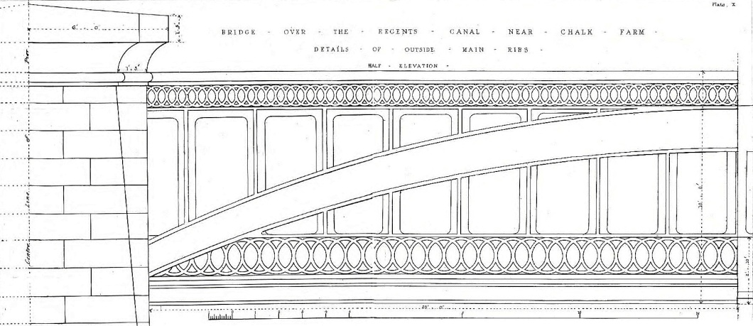
Above: half elevation for the bowstring bridge over the
Regent’s Canal, London and Birmingham Railway.
Below: the same bridge as depicted by John
Cooke Bourne, May 1837.
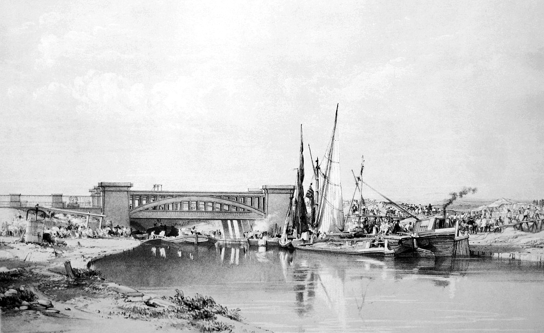
|
“This is one of the
boldest specimens of construction on the whole line, the Railway
being entirely suspended by attached rods, as shown upon the several
plates. We believe it is the first application of the
suspension principle to carry locomotive engines and trains as used
upon a Railway.
The railway platform contains four lines of rails, and is hung on
wrought iron suspension rods, which are supported by massive cast
iron main beams, of which there are three pair, well braced
together, and spanning the canal by a length of 50 feet, and at an
elevation of 12 or 13 feet above the level of the water. These
beams are cast with a flat arch rising in their depth, and strong
horizontal tension rods, well coupled, are fixed to counteract any
inclination of the ribs to spread at the abutments. The
Railway platform consists of a number of fish bellied girders, each
28 feet long, and which are supported by the suspension rods and
laid athwart the bridge. These rods are securely keyed to the
main beams. Oak beams are fixed across the girders upon which
the railway chairs are secured, and cast iron gratings are filled in
between the spaces, which complete the bridge.”
Railway
Practice: A Collection of Working Plans and Practical Details of
Construction, S. C. Brees (1859).
The following is a section from the contract specification:
“This Bridge will consist of three Main
Ribs of cast iron, properly secured. Each main rib will
consist of two ribs, properly connected, and each of these will be
cast in one piece. The Cross Girders will be secured to these
ribs, and the thrust of the arch sustained by tie bolts. The
open Ornamental work of the face will be bolted to the main ribs,
(vide Plates 11 and 12). The Roadway Plates to be fixed as
drawing (vide Plates 11, 12, and 13), and they will be perforated
for drainage. No ballasting will be laid on the bridge.
The Chairs will be fixed on oak blocks, firmly secured to the
girders.
Coffer Dams will have to be sunk by the Contractor at his own
expense, and included in the amount of his tender, in order to get
in the foundations of the abutments. Concrete will be employed
in these foundations, as shown on the drawings. The Abutments
will principally consist of brickwork, set in mortar, (except so
much as is included between the foundations and the level of 1 foot
above top water level, for 18 inches from the face of the work,
which must be set in Roman cement.) The abutments will be
faced with stone, and stones will have to be built and bonded in
various parts, as shown on the drawings.”
Railway
Practice: A Collection of Working Plans and Practical Details of
Construction, S. C. Brees (1859). |
CHAPTER
6
――――♦――――
|
FOOTNOTES |
|
1. |
Generally speaking, ‘ruling grade’ on a railway is usually
synonymous with ‘maximum gradient’. Although the ruling
gradient on the London and Birmingham Railway was 1 in 330 (16 feet
to the mile), the short Camden Incline down to Euston Station
(initially cable worked) was far steeper, descending . . . .
“. . . . from the terminus at Euston
Square for 12 chains, at 1 in 156, is then level for 13 chains, and
the succeeding 59 chains are divided into four gradients ascending
to Camden Town at 1 in 66, 1 in 110, 1 in 132, and 1 in 75
respectively.”
The
Practical Railway Engineer,
G. D. Dempsey (1855) |
|
2. |
Averaged out
over the entire length of the London and Birmingham Railway, the
volume of earthworks (cuttings and embankments) is estimated to have
amounted to 142,000 cu yards per mile (Page 102, The Practical
Railway Engineer, G. D. Dempsey (1855)) |
|
3. |
Where the
material to form an embankment could not be obtained from nearby
cutting or tunnel workings, it had to be excavated from the adjacent
land on either side of the line. The locations from where it
was dug became known as ‘borrow pits’. |
|
4. |
Because
the outside walls sloped slightly inwards, they were better able to
resist the internal outwards thrust from the centre of the
formation. The top of the embankment was profiled at the end
of construction. |
|
5. |
Abstract of
Evidence on the Great Western Railway, given before a Committee of
the House of Lords, June, 1835. |
|
6. |
“COUNTERFORT,
a pier or buttress, generally applied at the back of retaining walls
in modern civil engineering, for the support of the same, and
likewise for the purpose of forming a tie to the material at the
back of the wall. Counterforts are also sometimes carried up
on the face of a wall.”
A Glossary
of Civil Engineering,
S. C. Brees (1841). |
|
7. |
Rugby Viaduct
(Grade II listed). This structure, comprising 11 elliptical
arches, is around 700 feet long and spans both Leicester Road and
the River Avon. Opened in 1840 by the Midland Counties
Railway, it is one of the country’s oldest disused viaducts, forming
part of the first rail route between London and York.
Engineered by Charles Vignoles, it is built in red brick with a
facing of Staffordshire blue brindles and sandstone dressings. |
|
8. |
The Highway
(Railway Crossings) Act, 1839, required railways companies to build
and maintain gates at level crossings over roads, and provide a
person to open and shut them. |
|
9. |
The situation
of having to cross a waterway on the level, or tunnel beneath it,
did not arise on the London and Birmingham Railway. |
|
10. |
William Chapman
(1749–1832), English civil engineer, developed the first methodical
technique for the design of skew arches, his ‘spiral method’ being
described in Rees’s Cyclopædia. Chapman considered the
arch to be a series of arch slices, parallel to the arch faces and
at an angle to the abutments. The arch soffit (the curved
underside) is drawn out into a flat plane, a parallelogram grid
drawn on this, and then these diagonal lines (each one representing
an arch slice) transferred to the centring of the constructed arch. |
|
11. |
On the
Construction of Skew Arches,
Charles Fox (1836); A Practical Treatise on the Construction of
Oblique Arches, John Hart (1839); A Practical and Theoretical
Essay on Oblique Bridges, G. W. Buck (1839). |
|
12. |
In a thrust arch
bridge, the vertical and horizontal forces are transmitted along the
arches, requiring substantial abutments and foundations to prevent
the arch from flattening. In a bowstring bridge, the deck
carries the horizontal forces in tension, thus the abutments need
only support the vertical load. This allows bowstring bridges
to be constructed with less robust foundations. |
|
13. |
This lay between
the Regent’s Canal, Gloucester Road (now Gloucester Avenue), the
western edge of Stables Yard and Chalk Farm Lane (now Regent’s Park
Road). |
|